
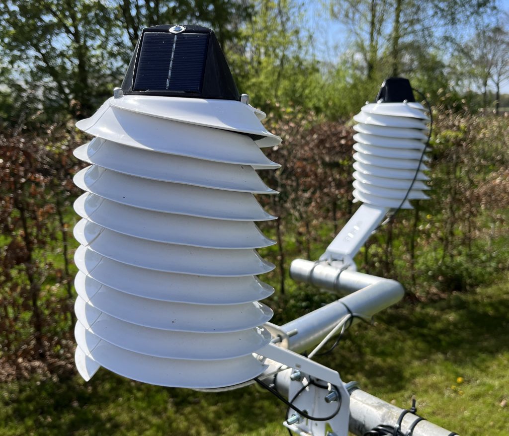
In this post, I explained how I use a Wemos D1 Mini microcontroller and a MOSFET module to control the fan speed of a wired fan-aspirated MeteoShield Pro from Barani Design. I am also testing a model with a fan powered by solar panels. Both come with two additional wires connected to a reed switch inside the fan. This allows for precise measurement of the current speed at which the fan is running.
How can we use these wires to get fan rpm? The principle behind it is very similar to the way rpm is calculated for the Apogee TS-100, or any fan for that matter. In a previous post, I go into some more detail about the tachometer on that model.
For both the Apogee and Barani models, the fan rpm can be calculated by counting the number of pulses emitted on the tachometer wire. The Apogee TS-100 emits 2 pulses per revolution. Counting the number of pulses per second and multiplying that by 30 gets the total number of revolutions per minute (rpm). Internally, the Barani FARS uses a reed switch which closes just once per fan revolution. By connecting the reed switch wires to a microcontroller, we can detect when the switch closes and makes a connection. As always, I use the Wemos D1 Mini for this.
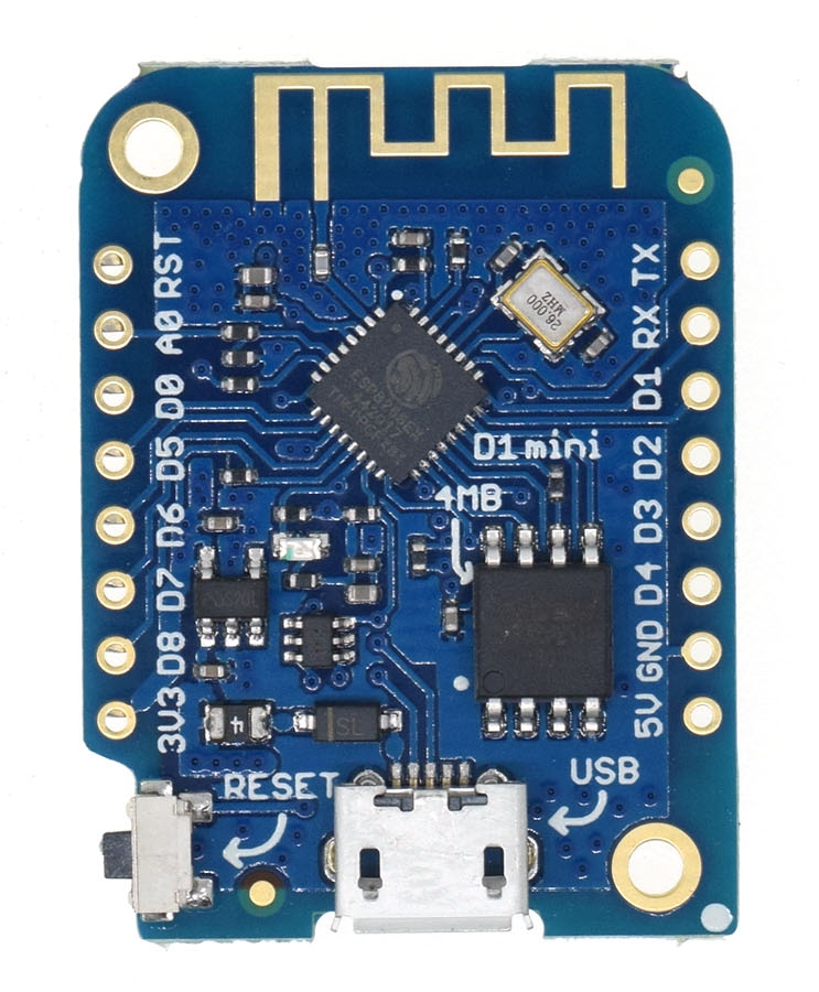
To achieve our goal, we need to use 2 pins on the Wemos. Ground (GND) and pretty much whichever digital pin is available. I just go with D1 (GPIO5) when available. The two wires should be connected to GND and D1.
The principle is this. First, pins like D1 have the ability to detect when a voltage level is applied to them. When this happens and the voltage is above a certain threshold, they will read ‘HIGH’. When there is no signal or the signal is below that threshold, the pin will read ‘LOW’. Second, whenever a pin is connected directly to ground it will read as low.
With those two facts in mind, we can initialize our D1 as reading high by connecting it to the internal voltage supply via a pull-up resistor. Whenever the reed switch closes, a connection is made between D1 and GND. Or, in other terms, D1 is pulled to ground. The internal voltage signal is redirected to ground. This causes D1 to switch from reading high to reading low. This event is what we can listen for.
So technically, in stead of a pulse we are actually detecting the lack of a voltage signal.
What does the code for this look like? As always any sketch contains a setup function.
void setup() {
   pinMode(5, INPUT_PULLUP);
}
The setup does one thing. It defines pin 5 (D1) as an input. The second parameter INPUT_PULLUP not only indicates this, but it also connects to the internal pull-up resistor just mentioned and makes the pin read high by default.
Before we get to the loop() function, we need to create a function which should run each time the reed switch closes and the D1 pin reads low. I’ve called that function ‘falling()’.
volatile int prevPulseTime = 0;
volatile long DURATION_SUM = 0;
volatile int SUM_COUNT = 0;

void ICACHE_RAM_ATTR falling() {

  long long microSecs = micros();

  long duration = microSecs - prevPulseTime;

  if (duration > 20000) {
    // if duration < 20000, assume reed switch bounce
    DURATION_SUM += duration;
    SUM_COUNT++;
    prevPulseTime = microSecs;

  }
}
Besides the function itself, I’ve defined 3 variables: prevPulseTime, DURATION_SUM and SUM_COUNT. Before I get to how it’s supposed to work, let me also add the loop() function.
void loop() {
  DURATION_SUM = 0;
  SUM_COUNT = 0;

  attachInterrupt(5, falling, FALLING);

  delay(2000);

  int avgPulseDuration = DURATION_SUM / SUM_COUNT;

  int rpm = 60000000 / avgPulseDuration;
  Serial.print("RPM: ");
  Serial.println(rpm);

  detachInterrupt(5);

  delay(30000);
}
The loop does the following. First DURATION_SUM and SUM_COUNT are reset to 0 at the beginning of each loop.
Then we call attachInterrupt() with mode ‘FALLING’. This tells the system to run the function falling() when pin 5 goes from high to low. Afterwards, the function falling() will be called on each revolution of the fan when a connection is made with ground and the pin goes low.
The falling() function is very simple. It requests the current number of microseconds (since the system booted). Based on the prevPulseTime – which is set each time the function runs – the duration between now and the last pulse is calculated. It then checks if this duration is more than 20000 microseconds. This is important, because reed switches have a tendency to bounce. That is, each time both sides connect, they can physically vibrate or bounce before they settle in position causing them to quickly disconnect and reconnect. If we don’t take this into account, all these bounces will be considered fan revolutions. This would result in an rpm calculation several factors too high. Whenever the time between pulses is less than 20000 microseconds, the pulse is ignored. If it’s more than that, it is considered a valid pulse and the duration is added to the sum, and the count is incremented by 1. Finally, the previous pulse time is set to be used for the next time the function is triggered.
Back to the loop. After attachInterrupt is called, a delay of 2 seconds is introduced. During these two seconds, an n number of pulses is processed. At the end of the two seconds, the average pulse duration is calculated by dividing the sum duration of the pulses by the number of pulses. Subsequently detachInterrupt is called, cancelling the listener on pin 5. A 30 second delay is introduced, after which the loop starts over and the fan rpm is calculated anew.
There are several ways to get to the same result. I’ve seen code that counts the number of pulses during a single second and then multiplies that by 60. The problem with solution like that, is that depending on when the second starts, you may end up with 1 pulse more or less. That then makes a difference of 60 rpm. I prefer some more accuracy.
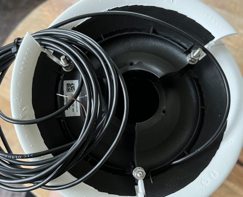
For the solar powered FARS, the actual code I use isn’t too far off from what I shared above. Below is an image of the hardware I have in place for this. For the wired FARS, reading fan rpm in the same manner can be combined with fan speed control. Each cycle then is a combination of checking the desired fan speed, updating the duty cycle based on the method described in this post, giving the fan a few moments to adjust and then reading the fan speed.