
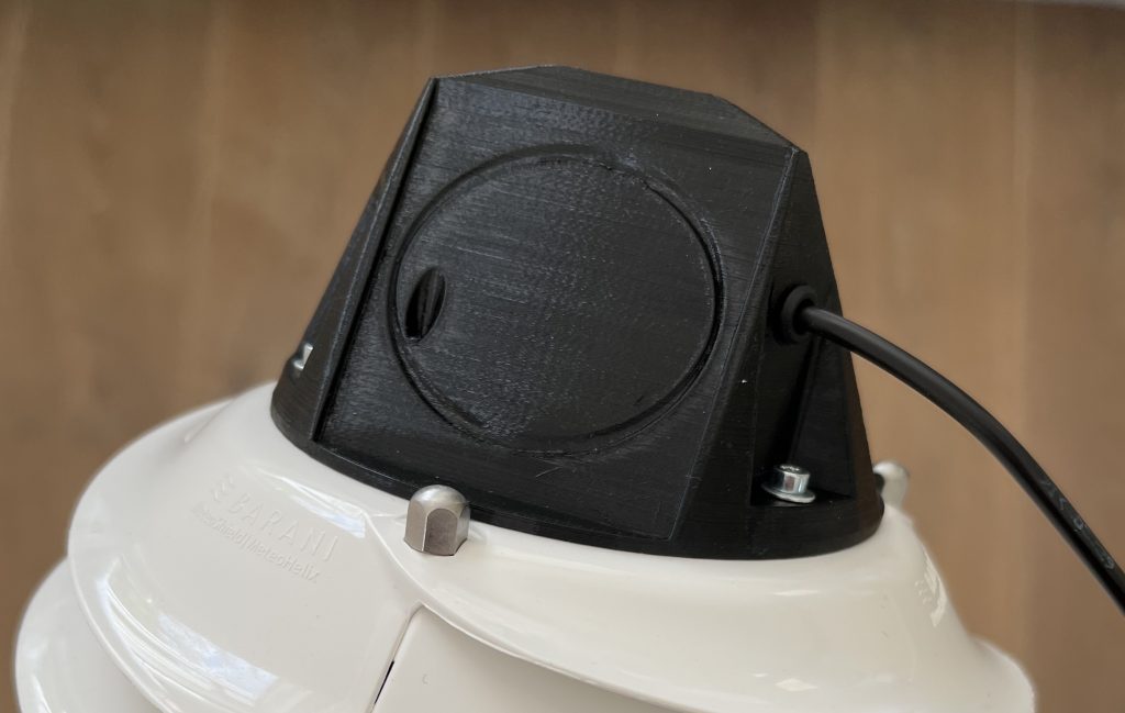
Recently, I was fortunate to receive a new prototype model of the fan-aspirated MeteoShield Pro from Barani Design. On this version, the solar panels are replaced with two power wires, making it possible to connect an external power source, allowing the fan to be active 24 hours a day. Varying fan rpm is possible by adjusting the voltage level being supplied to the fan. This makes a more elaborate comparison possible between the Barani FARS (fan-aspirated radiation shield) model and my Apogee TS-100, which is also an aspirated radiation shield.
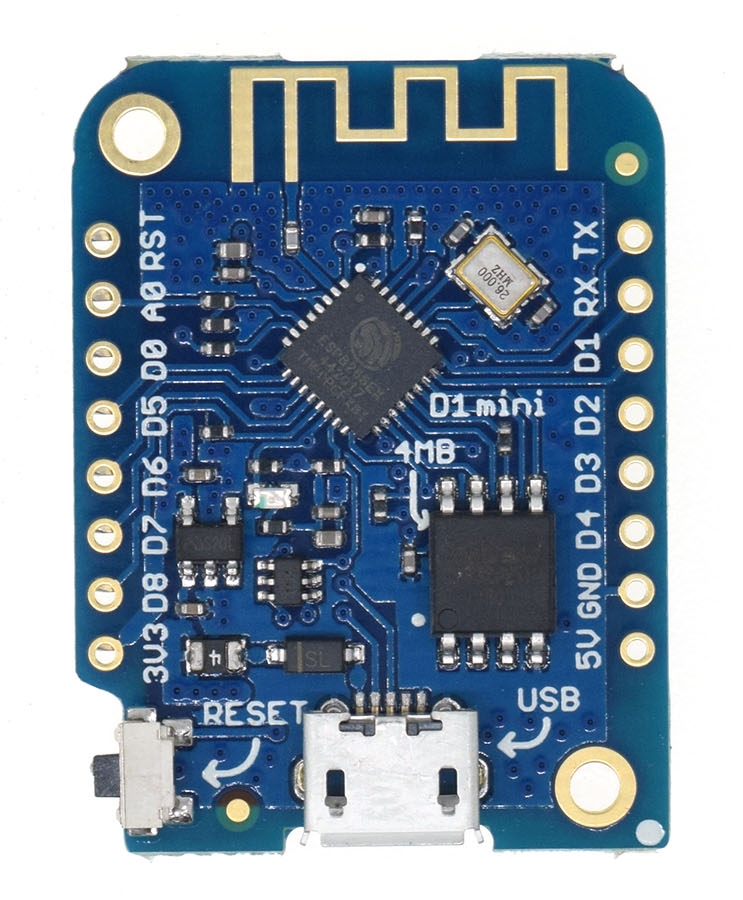
Since I have a 24 volt power line running up to my weather station, supplying the fan with the required voltage is no problem. I already have step down converters from 24 to 5 volts in place. This can serve as input for the fan. Controlling the fan speed requires a variable voltage from a desired maximum of 3 volts (~2500 rpm) down to the point where the fan stops running. Allowing a microcontroller like the Wemos D1 Mini to programmatically adjust the supply voltage is a little more involved.
How do we control a fan like this one?
An obvious candidate for controlling any DC fan is pulse-width modulation (PWM). As with the TS-100, PWM should allow me to control the fan speed. But there is an important difference between the fan types. The Apogee model came with two power wires as well as a dedicated PWM wire. This last wire allows the user to tell the fan directly how fast it should run based on the duty cycle of the signal. The prototype Barani model fan has no PWM wire. It only has the 2 power wires (not taking the tachometer wires into account, which are not relevant when considering how to power and control the fan).
Using PWM on the power input signal itself makes it possible to dictate average voltage supplied to the fan. DC fans are perfect for this. For example, if I were to set a duty cycle of 70% on a 3.3V input signal, I would be supplying 2.3V on average and the fan would be running slower. There is a caveat. The pins on the Wemos D1 Mini have a current limit of 40 mA. However, the fan in question is rated for up to 100 mA at the maximum fan speeds required. The Wemos board simply cannot supply voltage to the fan.
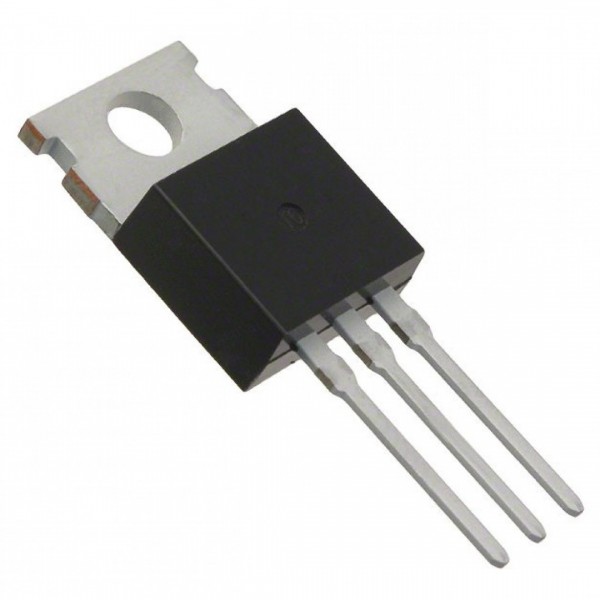
How to circumvent this problem? The answer is a MOSFET. This is type of transistor with 3 pins, which allows an input voltage to flow through it from a source pin to a drain pin depending on a voltage signal applied to a third gate pin. When there is no voltage applied to the gate pin, the flow is turned off. Putting voltage on the gate pin will cause the MOSFET to turn ‘on’.
More importantly, it is also possible for this gate signal to be a PWM signal. A duty cycle of 70% will cause the MOSFET to be ‘on’ for 70% of the time. This makes it possible to control not just the current flowing or not, but the amount of current that flows.
For example, assume that the output of the MOSFET is connected to the fan and the input voltage is 5 volts. If the duty cycle of the PWM signal is set to 60%, we can say that an average of 3 volts (0.6 * 5) is running to the fan. As far as the speed of the fan is concerned, a 60% duty cycle on 5 volts is the same as supplying 3 volts.
The gate signal can be controlled using a microcontroller like the Wemos D1 Mini. When selecting a MOSFET to use, it is important to consider the minimum voltage required for the gate signal. Many MOSFET’s will not work on 3.3V, the logic level of the ESP8266 chip on the Wemos board. The voltage available will not be enough to trigger the flow properly.
Luckily, there are several MOSFET’s that do work on lower voltages like 5 and even 3.3 volts. Even better, practical and cheap MOSFET modules exist which come with screw terminals soldered onto it. Like this one.
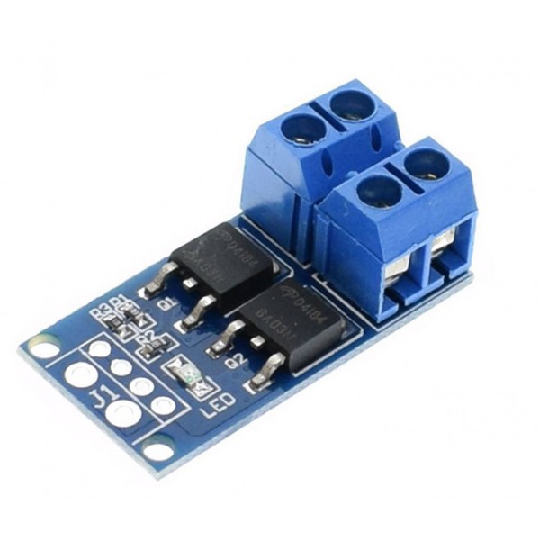
The module shown here is available for less than 2 euro’s a piece and works with a gate signal of 3.3 volts. Perfect for the Wemos board.
Wiring is simple.
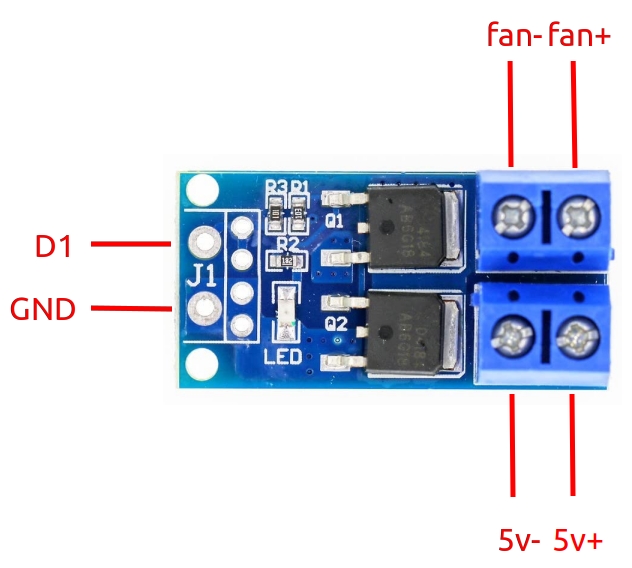
The connection for the in- and output speaks for itself. The signal pin on the module can be connected a PWM capable pin on the Wemos board. D1 or GPIO 5 works fine for this.
The principle for controlling the fan speed is very simple. The duty cycle on the signal from the D1 pin determines how fast the fan runs. Here is a simple sketch, just 10 lines of code, that sets the duty cycle to 60% on startup.
int PWM_PIN = 5; // D1

void setup() {
    pinMode(PWM_PIN, OUTPUT);
    analogWriteFreq(75000);
    analogWrite(PWM_PIN, 614);

}

void loop() {}
Let’s look at what happens here.
First, the pin we will use for the PWM signal is defined. This is 5 (GPIO 5), also D1.
The setup function calls the pinMode() function first. It tells the PWM pin D1 to behave as an output pin. It’s sending a signal rather than receiving it.
Then we define the frequency at which the D1 pin will be emitting its signal using the analogWriteFreq() function. (Not all microcontrollers have this function, I discovered. For example, the Arduino Nano does not allow you to configure signal frequency this way.) In the sketch, I set it to 75000 or 75 khz. It means that the pin will emit 75000 pulses per second. Frequency is relevant. At one point during testing I had the frequency set very low, at 50 hertz. The effect was that the fan started to make a very loud noise whenever I lowered the duty cycle, because the power was switching on and off only 50 times each second. I don’t know what the perfect frequency would be for this fan. Opinions seem to differ on the subject. At 75 khz, this specific fan appears to run very smoothly. I should also note that the MOSFET module I linked to has a limit of 20 khz in the description. I am unsure if that also applies to the one I purchased from a different seller. I may use a logic analyzer at some point to confirm the frequency of the output signal. Perhaps it is capped at 20 khz regardless of the frequency of the input signal.
Last, analogWrite() is called. We pass 2 values to that function. First the parameter value for PWM_PIN: D1. Second is the value for the duty cycle. When using the function on the Wemos, that value can be anyting between 0 (0%) and 1024 (100%). (Other Arduino-type boards may may have a different maximum numeric value) For example, when I want to set the duty cycle to 60%, the value should be 614 (0.6 * 1024).
The analogWrite() function can be called inside the loop as well, making it possible to update the duty cycle whenever the loop runs. In my case, my meteodrenthe.nl server determines the desired fan speed based on time of day and current solar radiation. The Wemos queries for this value each minute and adjusts the duty cycle accordingly. Since my input is 5 volts and I do not want the voltage supplied to the fan to exceed 3 volts, I hard coded the maximum duty cycle to be set to 60%. This results in a fan speed of 2500 rpm. A duty cycle of roughly 15% puts the rpm around 1000.
Of course, how the desired fan speed is determined and how often – if at all – the duty cycle is updated entirely depends on the requirements of the setup. There are many different fans with varying specifications. The Wemos D1 Mini combined with the aforementioned MOSFET module should be able to handle all available 5V, 12V or 24V fans.