
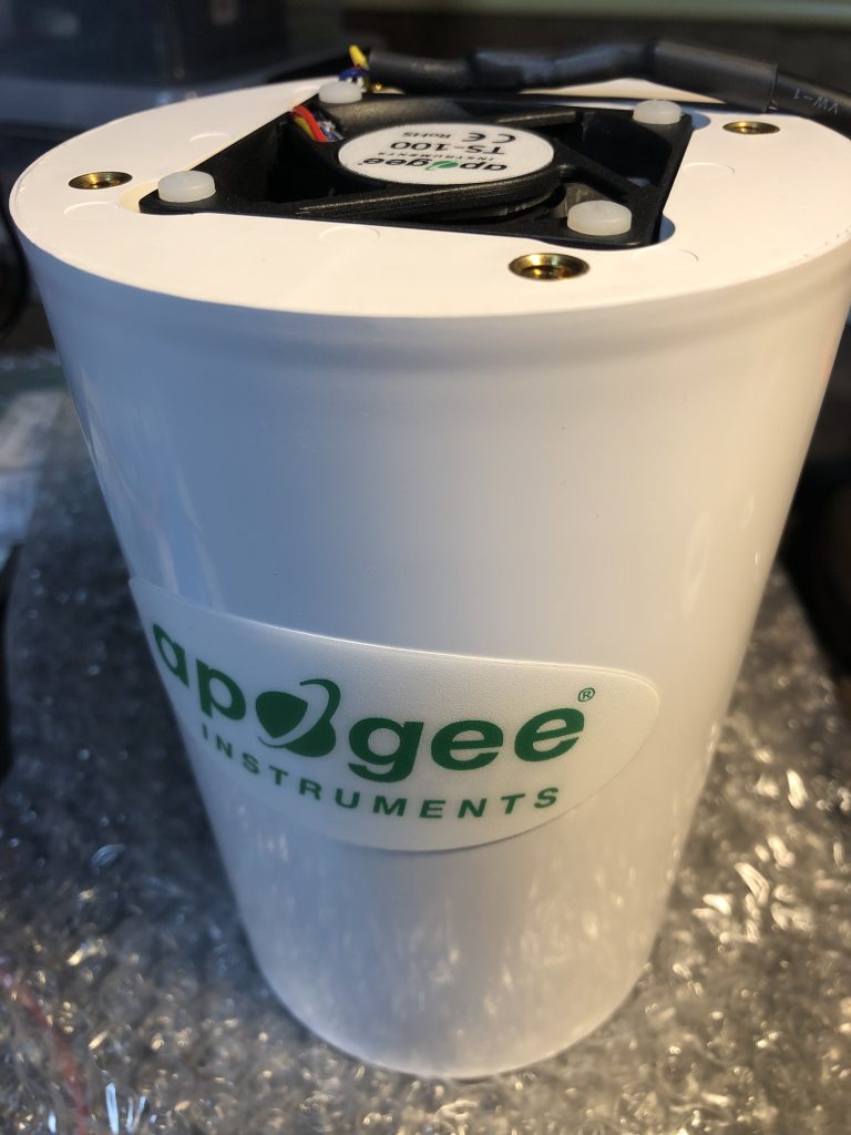
In my previous post I addressed the power supply needed to run the Apogee Instruments TS-100 fan aspirated shield in my setup. The next step is building a controller for the fan that allows me to vary the fan speed and read the actual rpm being achieved. The idea is that the controller can query the Meteodrenthe API server which then responds with a percentage value at which the fan must run given the current weather conditions. Tweaking the algorithm which yields this percentage will be a big part of the fun after the shield is up and running.
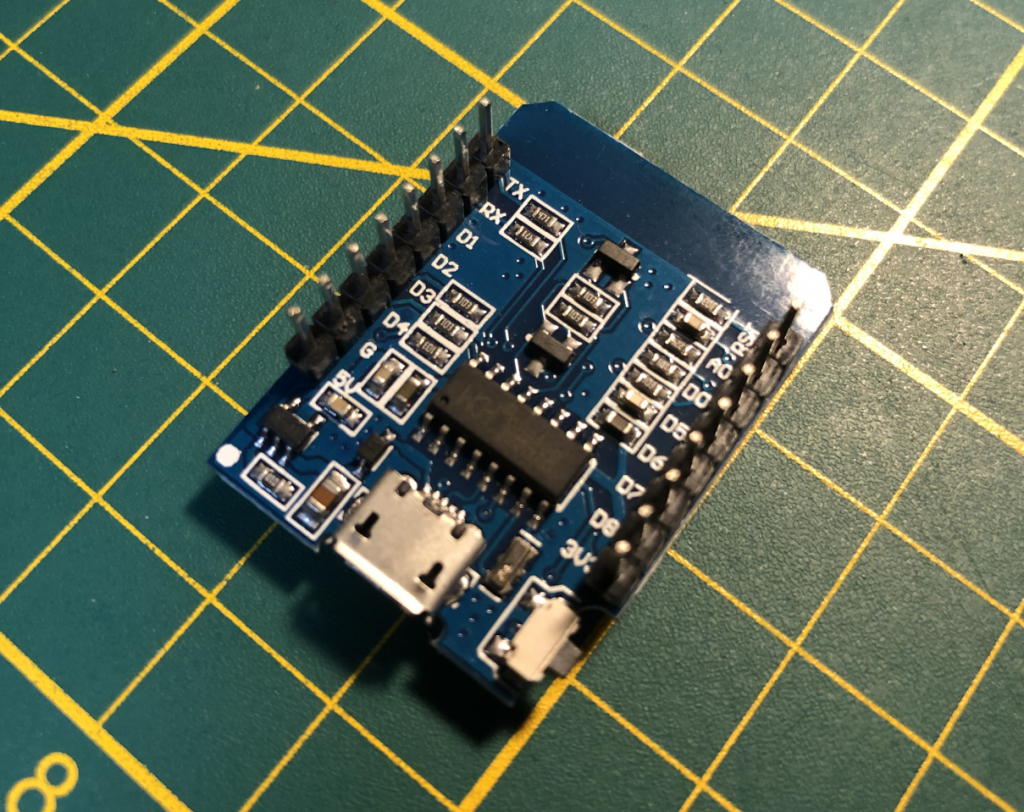
For now the objective is just the ability to control the fan. For this goal I will use, once again, a Wemos D1 Mini board. I assume that the reader has a basic idea of this Arduino compatible board and the process of writing an Arduino sketch in a program like the Arduino IDE.
Fan wiring
All important before we begin, is the documentation for the TS-100. Page 13 explains fan operation. Here is an image of the fan wiring.
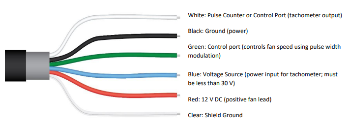
The red and black wires power the fan. They will be connected to the power source discussed earlier. The specification sheet tells us that the input voltage should be between 10.8 and 13.2 V DC.
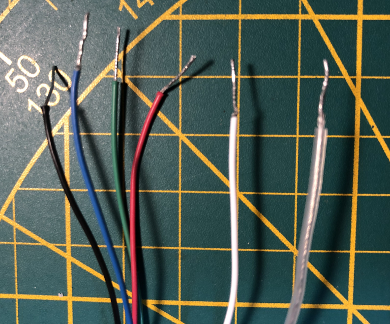
For control, the other 4 wires are involved. I connected them to the Wemos D1 as follows.
| TS-100 | Wemos D1 |
|---|---|
| Green (fan control) | D5 |
| Blue (tachometer input) | D6 |
| White (tachometer output) | D7 |
| Clear (ground) | G |
I used D5 through D7, but any digital pins other than D0 are fine to use for the current purpose. You may want steer clear of D8, since putting voltage on that pin will cause the boot of the Wemos to fail.
Fan speed control
Let’s start with the green wire. The documentation tells us that we can vary fan speed with pulse width modulation (PWM). See some basic explanation here. Bottom line is that we should adjust the ‘duty cycle’ of the signal (how much of the time the pin on the Wemos is ‘on’ or ‘high’) depending on how fast we want the fan to run the fan. The Apogee documentation says that a 50% duty cycle is low power (~2500 rpm) and 100% is high (~4500 rpm). Anything between or lower will also affect fan speed, so running at 25% or 75% is also possible.
To emit the correct signal, we can use the function analogWrite(). This allows us to adjust the duty cycle for a specified pin. For the Wemos board, the max value is 1023 (100%) and half that value (512) is, you might have suspected, 50% duty. The PWM documentation above mentions 255 as the max value, but this only applies to the Arduino, not the Wemos.
(Update 2023-09-21 I recently noticed that since ESP8266 Arduino core version 3.0, a breaking change was introduced in which the range for analogWrite() was changed to 8-bit to align with standard Arduino libraries. So depending on updates, the Wemos board now also expects a value between 0 and 255.)
One last thing is that the documentation says the signal should have a frequency of roughly 20 kHz. This can be achieved by using the analogWriteFreq() function, which accepts a frequency value in Hertz.
The simplest version of a sketch that changes fan speed is this.
int PWM_PIN = 14; //D5

void setup() {
    // set frequency to 20 kHz
    analogWriteFreq(20000);
    // set duty cycle to 50%
    analogWrite(PWM_PIN, 512);
}

void loop() {}
This code defines the int value of the D5 pin, which is 14. Upon setup, the board is instructed to emit signals at a frequency of 20 kHz, after which the duty cycle of the D5 pin is set to 50%. Immediately, you will hear the fan rpm dropping. If you are using a variable power supply with a display showing amps, you will see the current draw drop from close to 80 mA to something closer to 25 mA (in my case just over 30 mA).
Tachometer input
Next up is the blue wire, the tachometer power input. This allows you to dictate the max voltage of the white tachometer output wire. All that is needed here is to put some voltage on this wire at a level the Wemos can handle. In my case I connected the blue wire to D6 and simply turned it on.
int TACHO_PWR_PIN = 12;// D6

..

analogWrite(TACHO_PWR_PIN, 1023);
Here I define the tachometer power pin as 12 (or D6) and set that pin to the max value of 1023 in the setup stage using analogWrite().
Tachometer output
Last comes reading the actual rpm of the fan. This is slightly more complex. Rpm is read by counting the number of pulses the tachometer emits. The tachometer will emit a certain number of voltage pulses (turn voltage on and off) per second depending on the speed of the fan. The Wemos board can read these pulses and determine the frequency. That value should then be multiplied by 30 (as per the documentation) to yield rpm.
To get a better idea of what this means, this is a visualization of the square wave signal at 50% duty cycle as captured by a logic analyzer.
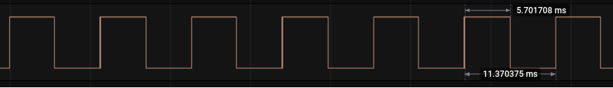
You can see that the duration of a pulse (from the moment the voltage rises, through the low up until the next moment the voltage goes high again) is roughly 11.4 ms. That means the tachometer is emitting 87.7 pulses per second (87.7 Hertz). Multiply that by 30 and you end up with 2631 rpm. This is about the value that is expected, since the documentation says we should get around 2500 rpm at 50% duty.
For comparison, max speed (100% duty) yields the following wave.
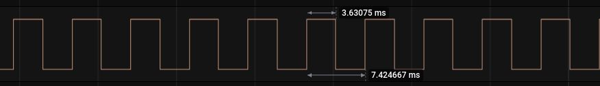
This signal pulses faster, at 7.4 ms per pulse. The resulting rpm (1000 / 7.4 * 30) is 4054.
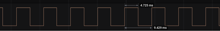
One last example. At 75% duty cycle the rpm is measured at 3191.
So, how do we measure these values with the Wemos board? There are several ways to achieve this. The principle is simple. We want to measure the time difference between the moment the signal goes high to the next moment the signal goes high. Then we measure the entire length of the pulse and we can calculate the number of pulses per second.
We can measure the moment the signal goes high by attaching an interrupt function to the D7 pin (which we’ve connected to the tachometer ouput wire, as indicated earlier) which triggers whenever the pin goes high. This is done using the function attachInterrupt(), which accepts a pin number, a function to execute when the condition is met and an enum value (in our case RISING) to indicate what that condition is.
The function we execute does two simple things: register the time in microseconds and calculate the time difference between now and the last registered time. So, we add the following to the code.
int IRQ_PIN = 13; // D7, this is our interrupt pin
volatile int pulseDuration = 0;
volatile int prevTime = 0;
..

attachInterrupt(IRQ_PIN, rising, RISING);

..

void rising() {
  pulseDuration = micros() - prevTime;
  prevTime = micros();
  int pulses = 1000000 / pulseDuration;
  int rpm = pulses * 30;
  Serial.print("RPM: ");
  Serial.println(rpm);
}
From top to bottom, we’ve done the following.
D7 has been assigned as the value of the interrupt pin. Two variables have been defined in order to register (1) the duration of a pulse and (2) the previous time recorded.
We have used attachInterrupt() the setup stage in order to execute the function rising() whenever the pin D7 goes high.
The function rising() itself uses the last recorded time to calculate the time difference between then and now. This is our pulse duration. Then the previous time is set to the current time. It is important to do this right away, because the following code takes a few microseconds to complete and we don’t want other processes causing imprecise registration of the time.
In order to not spam your serial log with too many print statements, you can include a counter and only log every 50 or 100 events or so.
int i = 0;

..

void rising() {
  pulseDuration = micros() - prevTime;
  prevTime = micros();
  i++;
  if (i % 50 == 0) {
    int pulses = 1000000 / pulseDuration;
    int rpm = pulses * 30;
    Serial.print("RPM: ");
    Serial.println(rpm);
  }
}
Running the code now at 75% duty will start printing the following lines to your serial monitor:
20:39:05.413 -> RPM: 3150
20:39:05.843 -> RPM: 3150
20:39:06.340 -> RPM: 3120
20:39:06.804 -> RPM: 3150
20:39:07.235 -> RPM: 3120
20:39:07.700 -> RPM: 3120
20:39:08.166 -> RPM: 3150
20:39:08.632 -> RPM: 3150
20:39:09.096 -> RPM: 3150
It is not exactly the same as the value 3191 we calculated using the logic analyzer, but it’s close enough.
At 50%:
20:42:23.261 -> RPM: 2550
20:42:23.759 -> RPM: 2550
20:42:24.290 -> RPM: 2550
20:42:24.855 -> RPM: 2550
20:42:25.419 -> RPM: 2550
20:42:25.952 -> RPM: 2550
20:42:26.551 -> RPM: 2550
20:42:27.050 -> RPM: 2580
20:42:27.617 -> RPM: 2580
Also fairly close to the 2631 we measured earlier.
Several adjustments make sense. Averaging a series of pulses may result in some more accuracy. The interrupt function should be limited to just setting the pulse duration and registering the time. It’s in the loop later on that we will want to use the rpm value and send it to a server along with the latest measurement of the temperature.
Whatever additional code is included depends on your objectives. In a future post I will expand the code to include querying my API server for the desired current fan speed, reading the temperature sensor and sending its value along with the current fan speed to my server.
For now, this is the sketch that allows full testing of the TS-100 fan.
int PWM_PIN = 14;//D5
int TACHO_PWR_PIN = 12;// D6
int IRQ_PIN = 13; //D7

volatile int pulseDuration = 0;
volatile int prevTime = 0;

void setup() {
  Serial.begin(9600);
  // execute rising() whenever the tachometer wire goes high
  attachInterrupt(IRQ_PIN, rising, RISING);
  // set frequency to 20 kHz as per TS-100 documentation
  analogWriteFreq(20000);
  // put some voltage on the power input for the tachometer
  analogWrite(TACHO_PWR_PIN, 1023);
}

void loop() {
  int duty = 1023 * 0.5; // duty 50%

  // write duty cycle to the fan control wire
  analogWrite(PWM_PIN, duty);

  delay(5000);

  int pulses = 1000000 / pulseDuration;
  int rpm = pulses * 30;
  Serial.print("RPM: ");
  Serial.println(rpm);

}

void rising() {
  pulseDuration = micros() - prevTime;
  prevTime = micros();
}