
A thermistor is a very common type of thermometer. They are cheap and readily available in many forms. Thermistors are simple devices. A thermistor is basically nothing more than a resistor that changes its resistance with temperature. Very popular are 10K NTC thermistors. Negative Temperature Coefficient (NTC) means that resistance drops when temperature rises. 10K refers to the resistance at specific temperature. Most of the time, it means that the resistance of the thermistor at 25 degrees Celsius is 10000 ohms. At temperatures lower than 25 degrees, resistance will be higher, and vice versa for temperatures over 25 degrees.
In order to get a temperature reading from a thermistor, we need its current resistance value. Resistance in an electrical circuit causes a ‘voltage drop‘. We can determine the resistance of any component by measuring how much an input voltage drops when it passes through it. In order to do that, we need to set up something called a voltage divider. Put into a generic schema, it looks like this.
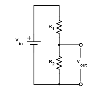
It is not terribly complex to set up. Adafruit has a great tutorial explaining basic wiring and code. As the schematic suggests, we need 4 elements to make a measurement work. Vin is the voltage input, which will be supplied by our Wemos D1 Mini microcontroller. R2 is the thermistor. To measure the voltage drop caused by the thermistor, we need a second resistor (R1) connected in series. Given a fixed value for that resistor, we can determine the share in the total resistance that the thermistor (R2) represents. To do so, we will also need the value Vout, which is the voltage ‘across’ R2. It is the voltage drop that is caused by the thermistor. Since we know the resistance of R1, we can calculate the resistance of R2.
The equation to calculate this value looks like this.
R2 = R1 / (Vin / Vout -1)
To determine R2, the resistance of our thermistor, we need the 3 other values. Let’s look at all of them in a little more detail.
First we need R1, which is the resistance of the other resistor connected in series with the thermistor. Using a 10K resistor is typical in most setups. Other values are also possible, but 10K allows for the best resolution in the measuring range you typically use a thermometer in (let’s say roughly -30 to 45). Most other resistance values for R1 will give you lower voltage ranges between the lowest and highest temperatures the thermistor will be exposed to. That would mean that each change in temperature would be represented by a smaller amount of millivolts. That’s not a terribly big deal, but the more the better right?
Next, we need Vin. This will typically be 3.3 volts, the logic level for the Wemos D1 Mini. As it turns out, this is less straight forward than you might think. More on this below.
Last, we need Vout. This is the voltage ‘between’ R1 and R2 or ‘across’ R2. It is the voltage drop caused by R2, the thermistor. Or, in other words, the share of the total voltage that is remaining after passing through R1. Whenever the resistance of the thermistor increases or decreases, so does the voltage drop.
In order to read voltage, we need an analog-to-digital converter, or ADC. It converts voltage to a numeric value we can use. The Wemos board has such a converter. Pin A0 allows us to read a voltage input. However, the resolution of the converter is only 10 bits. That means that the entire voltage range from 0 to the maximum 3.3 the analog input can handle is represented by only 1023 steps. Because our temperature range of interest represents only a part of the full range of the thermistor, we won’t be using more than 2 volts (and probably a bit less even, as I will point out shortly). That means we have only about 600 of those 1023 values to work with. If those 600 values must represent a range of 75 degrees (-30 to 45), we are looking at a resolution of 75 / 600 = 0,125 degrees.
Some might argue that the precision of any thermistor isn’t any better than that anyway. But my experience has been that under the right conditions, thermometers tend to agree with each other within a few hundredths of a degree most of the time. In my opinion, lack of resolution is something that needs to be addressed. We need to improve resolution, and that requires a better ADC. Adafruit has a 16-bit ADC available.
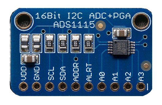
The ADS1115 has an I2C interface and has 4 analog input pins that can measure a voltage. For reasons stated in the documentation, when using all 4 analog inputs (single-ended mode) we are limited to 15 bits. 15 bits means 32768 steps in stead of 65536. That is not a limitation, though. Using this singled-ended mode means we cannot read negative voltages, thereby eliminating half of the range anyway. For positive voltages, -4 to +4 volts at 16 bits results in the same resolution as 0 to +4 volts at 15 bits.
A ‘gain setting’ also allows us to configure the expected voltage range. This allows for optimizing resolution. In our situation, we are forced to opt for a gain setting which assumes a range of +/- 4.096 volts. At 15 bits and a range that starts at 0, that means a resolution of 0,125 mV. (4096 mV / 32768 steps)
As mentioned, we cannot use the full 0 to 4.096 V range, however. For the range to truly start at 0, the resistance of the thermistor would have to be 0. Since the resistance of a typical 10k thermistor at the highest temperatures we can expect will be no less than around 5000 ohms, the starting point will be around 1 volt. The hypothetical realistic maximum resistance will be perhaps 100.000 ohms. That resolves to 3 volts. As a consequence, even though the ADC can read 0 to 4 volts, it will only ever be exposed to 1 to 3 volts. Our entire temperature range will be represented by a value in that voltage range.
So, considering we are using only 2 volts of those 4, we will only be able to use about 50% of the 32768 steps. Let’s round that down to 16000. If we then take our 75 degrees range, that gives us a resolution of roughly 0,005 (75 / 16000). That’s more than enough. I don’t register temperature at more than 0,01 resolution anyway.
With the ADS1115 we have a way of getting a Vout value with a good resolution. We’ll get to how we get the actual value from our ADC in a bit.
We have all we need now to calculate R2 and get the temperature value associated with it. Let me get down to how we convert the R1, R2, Vin and Vout to temperature.
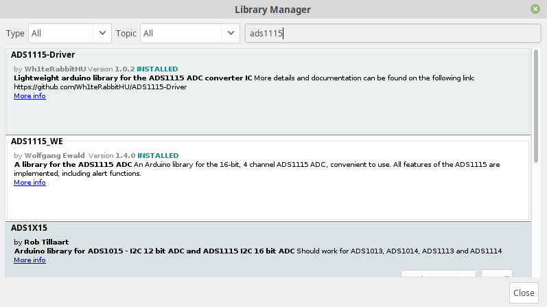
Most of the following is based on the Adafruit tutorial mentioned. I’m jumping ahead to the end, where we use the ‘B parameter equation‘* to get our desired result. Below is the minimal code required to get to a temperature reading. I’m using Arduino IDE for this. All that is needed besides these lines of code is a library that allows you to interface with the ADC. These are the options available. In my code, I use the ADS1X15 library.
The partial sketch, which can be part of the loop function:
int16_t adc = ads.readADC_SingleEnded(0); // read from A0

Serial.print("Raw adc: ");
Serial.println(adc);

float volts = ads.computeVolts(adc); // calculate voltage

Serial.print("Volts: ");
Serial.println(volts, 3);

float val = 3.3 / volts - 1;
float resistance = SERIESRESISTOR / val;

Serial.print("Thermistor resistance ");
Serial.println(resistance);

float steinhart;
steinhart = resistance / THERMISTORNOMINAL;
steinhart = log(steinhart);
steinhart /= BCOEFFICIENT;
steinhart += 1.0 / (TEMPERATURENOMINAL + 273.15);
steinhart = 1.0 / steinhart;
steinhart -= 273.15;

Serial.print("Temperature ");
Serial.print(steinhart);
Serial.println(" *C");
The code above requires a few fixed values.
SERIESRESISTOR is the resistance value of R1, which is 10000. THERMISTORNOMINAL is the resistance of the thermistor at 25 degrees, which is also 10000. TEMPERATURENOMINAL is 25. Then we have BCOEFFICIENT, which is the ‘B value’ of the thermistor. This is a value that should be part of the specifications. In my case the value is 3950. It’s usually a value between 3000 and 4000.
Running this code will print something like this.
10:07:32.021 -> Raw adc: 14036
10:07:32.021 -> Volts: 1.755
10:07:32.054 -> Thermistor resistance 11352.31
10:07:32.087 -> Temperature 22.17 *C
So what does the code do?
First the A0 pin from the ADC is read.
int16_t adc = ads.readADC_SingleEnded(0);It yields a value of 14036. The corresponding voltage is 1.755 volts. (4096 / 32768 * 14036 = 1754.5, rounded to 1755 mV or 1.755 volts)
After that, we use the equation mentioned earlier is used to determine R1.
That equation was R2 = R1 / (Vin / Vout -1).
float val = 3.3 / volts - 1;
float resistance = SERIESRESISTOR / val;
So we are calculating 10000 (ohms) / (3300 (mV) / 1754.5 (mV) – 1). The result is a resistance value of 11352.31. This is higher than the resistance at 25 degrees (10000), so we expect a temperature value of less than 25 degrees.
Finally the mentioned ‘B parameter equation’ is used to get our result. This part of the code is identical to that of the Adafruit tutorial. The resulting temperature value is 22.17 degrees.
A final complication
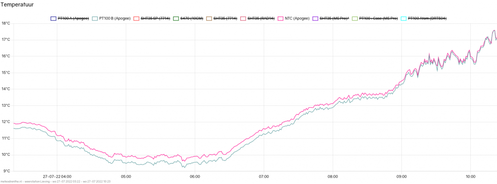
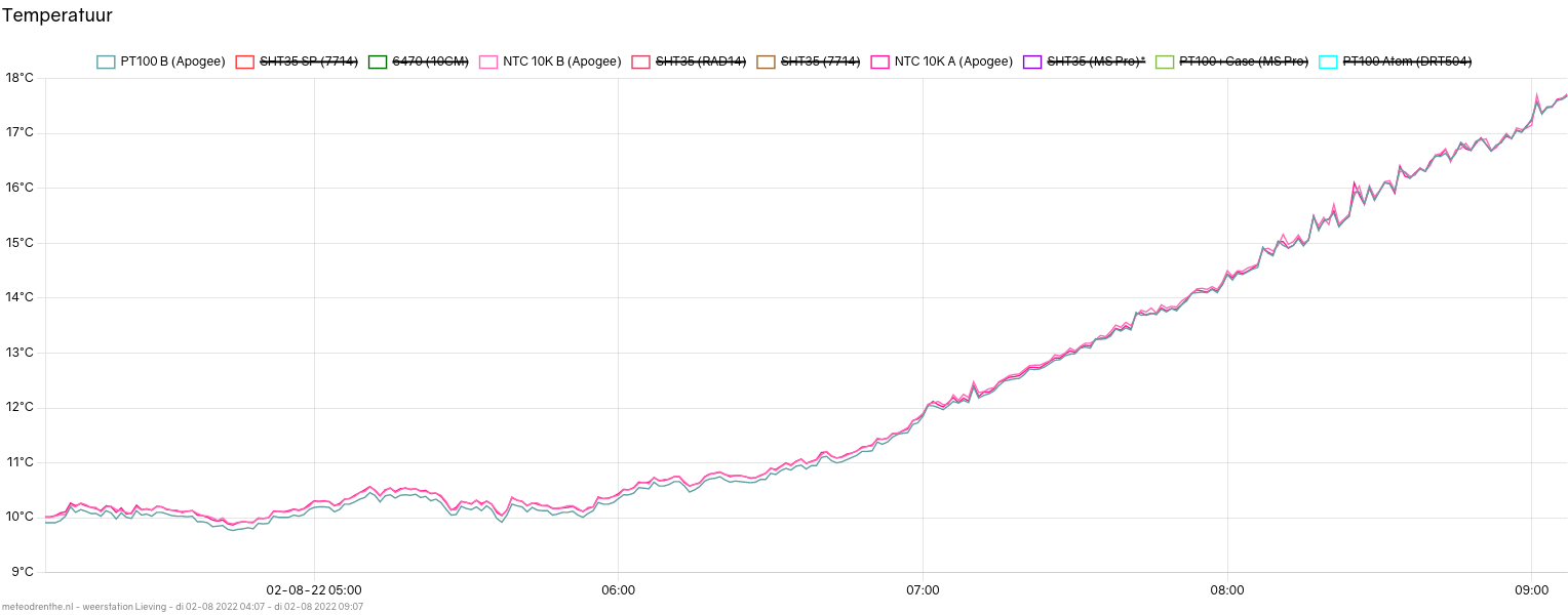
There is one final complication which needs to be addressed. When running tests on this setup, I compared the results of the thermistor with two PT100 sensors in the same actively ventilated radiation shield. During the day, when temperatures fluctuated between 16 and 21 degrees, both sensor types were in agreement. To such a degree that is surprised me, in fact. However, as can be seen in the graph below, whenever temperatures dropped below 15 degrees or so, the thermistor (in pink) started reading higher than the PT100. The difference seemed to increase with temperatures falling, up to as much as 0,4 degrees below 10 degrees Celsius.
This baffled me for a few days until a colleague pointed me in the right direction. I came to realize that the voltage supplied by the Wemos board is not always 3.3 V. When you measure it at any given time, output is very constant. However, with higher temperatures, it appears, that 3.3 slowly becomes 3.31. In the evening, when temperatures drop, my multimeter will read values like 3.297 V. My assumption is this will go towards 3.29 volts or less when it gets colder out during the night. The problem, simply put, is that Vin is not constant. So our calculation of R2 is going to be off if we use a hard coded value of 3.3.
For example, if we take our reading of 1.755 V (1754.5), our calculated resistance was 11352.31 if we assumed an input of 3.3 V exactly. However, if the input was actually 3.31 volts, and we use that as our input, the resulting resistance is 11279.33. That’s a difference of over 70 ohms. The first resistance value yielded 22.17 degrees. If we use the second value, we get 22.32 degrees. At the other extreme we might get a value of 3.29 volts. That gets us 22.0 degrees. 20 millivolts might not seem a lot, but it’s a difference of over 3 tenths of a degree in our calculation. (By the way, I use this website to do quick calculations for temperature.)
Luckily, we already have everything we need for a solution. All we need to do, is use one of our available ADC pins to measure the voltage the microcontroller is actually supplying at the moment the resistance is being measured. The PCB I designed did not take this into account, so I had to reroute a wire and bypass one of the fixed 10K resistors.
Our code is changed slightly. Assuming we are reading the voltage input on A3:
int16_t adc3 = ads.readADC_SingleEnded(3);
float vin = ads.computeVolts(adc3);

//

float val = vin / volts - 1;
float resistance = SERIESRESISTOR / val;
The effect of this adjustment is a clear improvement. I have been able to test the range of roughly 9 tot 29 degrees since then. Here we have temperatures from early morning on.
You can see that there is still some divergence. The difference at temperatures below 10 degrees is still about 0.1 degrees. But this is a big improvement from the 0.4 we had before. It probably makes sense, considering we just calculated that the voltage input differences explain about 0.3 degrees.
This is the situation during the day.
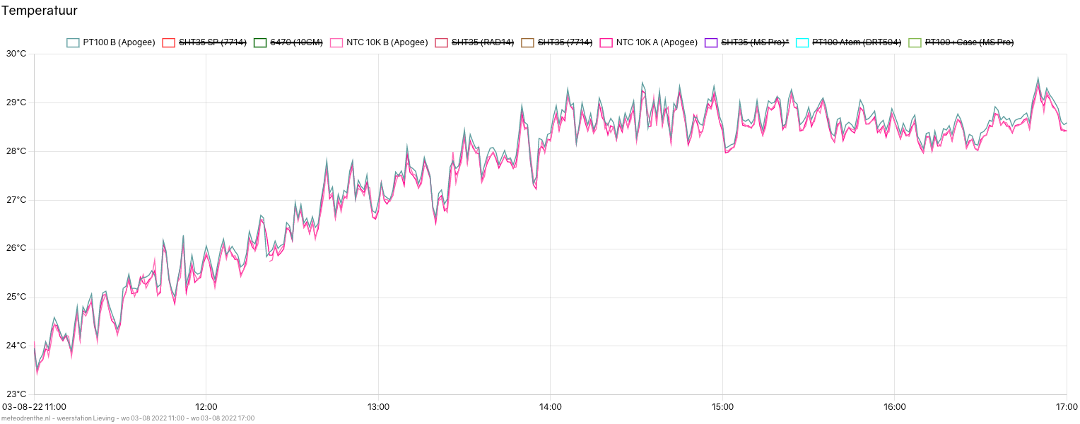
It’s a bit harder to see, but on average the thermistors are now reading about 0.1 degrees lower. My suspicion is that, should temperatures rise even further, the difference will increase. The same is probably the case for colder temperatures.
I cannot yet explain this behavior. Perhaps it is a limitation of the equation being used. In order to exclude some possibilities, I have ordered several thermistors with higher precision. (0.2% as opposed to the 1% I have been using) Also, the manufacturer of this thermistor supplies a datasheet with a table listing the resistance per degree of temperature. This should allow me to do a more precise calculation. Whether this will make a difference is not clear for me at the moment.
One last remark, which has to do with self-heating of the thermistors. A good suggestion is to not have the thermistors permanently receive a voltage input. This can be done by using a different pin than 3V3 and only powering it when the measurement is about to be made. Though I do not think that self-heating is a serious issue, it is a flaw in my setup. Another advantage of using a different pin, is that we can opt to limit the output of that pin to a lower voltage than 3.3, which in turn means we could increase the gain setting on the ADC so we need not lose resolution.
There are still enough tweaks and improvements to be made. When I have more results, I will share them in a second post.
This is the hardware I have in operation currently for processing thermistor input.
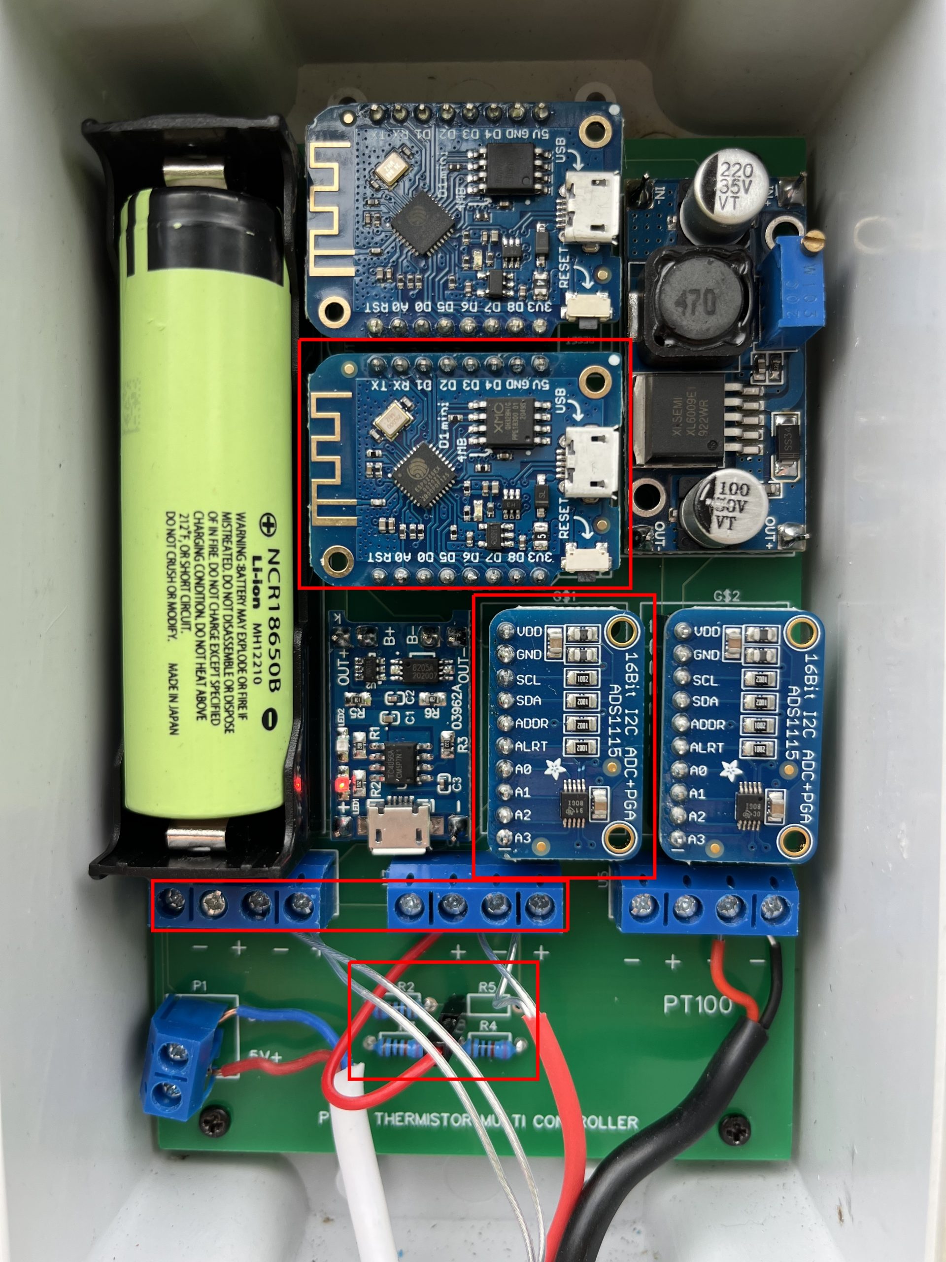
I have highlighted the elements responsible. (The other parts handle PT100 sensors. I wrote a different post on that subject.)
From top to bottom we have the Wemos D1 Mini microcontroller, the ADS1115, screw terminals for connected the thermistors and, at the bottom, 3 0.1% 10K resistors. Notice one empty resistor slot R5 and the red wire going directly to one of the screw terminal inputs. This redirects the voltage input that would normally go to one of the thermistors directly back into one of the analog inputs of the ADC. In a future iteration of this PCB I will have changed the design so the voltage input goes directly to one of the analog input pins.
* Update 07-09-2022: In this post I look into the B parameter equation being used in the sketch. Using the preferable alternative, the Steinhart-Hart equation, gives significantly better outputs.