Project Apogee requires me to rethink the power supply of my weather station. When I start writing this, the Meteodrenthe weather station runs on solar power only. The Davis components have their own panel inside the transmitters. Other custom elements use 2 watt 6 volt panels by Voltaic Systems. This has been an ideal solution until now.
Power usage
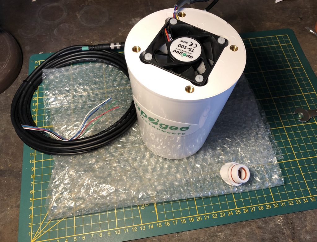
My planned Apogee Instruments TS-100 fan aspirated radiation shield will require more power than anything I have running right now. Even though the fan only requires 80 mA at maximum speed, it is still many times more than my power-optimized controllers for the SHT35 sensor I have in use. Those controllers only wake up twice a minute to read the sensor and forward the data. The rest of the time, the Wemos boards are in deep sleep mode. That way they can keep running on a single 4.2 volt 18650 battery for a at least a couple of weeks.
At 80 mA, a battery with a 3000 mAh capacity should drain within a day and a half. Consider that the TS-100 runs at 12 volts, so I’d have to run 3 or 4 batteries in series to get the required voltage. Expanding capacity would mean a sizable battery pack. Besides the fan, I may need to power an extra Wemos D1 Mini controller which can vary fan speed. (This is done using pulse width modulation, which I will cover in a later post) I want to be able adjust the speed to see the effects of varying the speed has on measurements. I have not checked how far I can reduce current draw on the Wemos D1 Mini while still being able to send the required signals, but I assume that even in modem sleep mode, at least an additional 10-20 mA would be involved.
I am unsure how much of its maximum capacity a solar panel can produce on cloudy days in December or January at my latitude (Northern Europe). But keeping in mind that even the ‘larger’ small solar panels produced by Voltaic only have a peak current of somewhere between 500 and 1000 mA, I am probably looking at a series of panels or a completely different approach to my solar power source. This seems like a lot of effort and no cheap option.
24 volt cable
This caused me to reconsider the need for solar power. Until now it was the practical solution. However, a power cable through the ground in my situation only has to cover about 17 meters mostly easy terrain. I decided this is so much cheaper and ultimately easier to realize.
After briefly playing with the idea of 220 AC voltage straight from the net, I settled on 24V DC. When working with higher voltages, that immediately involves dangers you need to consider. At 24 volts, I can run the cable a few inches into the ground without issue in most places. And that voltage is enough for anything that I will conceivable be running around my weather station, including possible snow heaters or camera’s.
For this I used:
- Flexible cable conduit
- 2 wire cable
- A fish tape / draw wire
- 24 volt power supply
The conduit is only used to protect the fragile cable. The fish tape (I was surprised that is what it’s called in English) is used to draw the wire through the cable. This was slightly more trouble than expected. Initially, I used a steel one, but it kept getting stuck half way in due to friction between the insides of the not so smooth conduit and the fish tape. I ended up using a (cheaper) nylon version, which is smoother than the steel one, and eventually slid through.
There are many options to choose from when looking for a 24 V power supply. Most of them are called LED power supplies it seems. Apparently that is a prevalent usage for 24 volts. The supply I chose comes with a 2 pin terminal block at the end, which I can connect directly to the cable. The 6 amps is be more than enough for my projects.
Step down converters
The other side of the cable is a bit more interesting. I need to split the cable to supply multiple controllers, all running at 5 volts. However, the TS-100 fan requires 12 volts. I decided to build on my good experiences at JLCPCB, and put together my own board with room for at least 2 step down converters which step down voltage from 24 V to 12 and 5 volts, as well as a couple of terminal blocks with can supply the power to any project requiring it. Delivery speed from JLCPCB is very good. This is an example of the result I received in the mail last week.
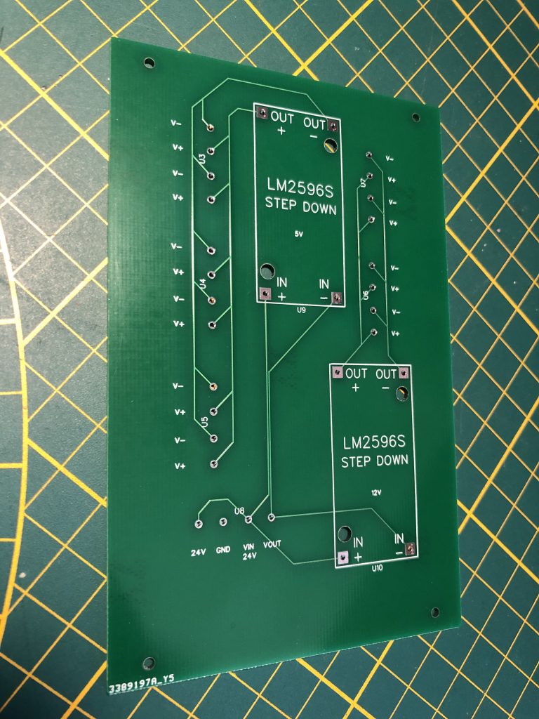
Observe the 24 V input/output at the bottom (I added an two extra pins should I want to lead the 24 volts somewhere else too in the future) with 2 tracks leading to the step down converters. The output for the converters then leads to holes where the terminal blocks go. There is room for 6 on the left and 4 on the right. The PCB is designed to fit into a specific water proof box available here on Amazon.
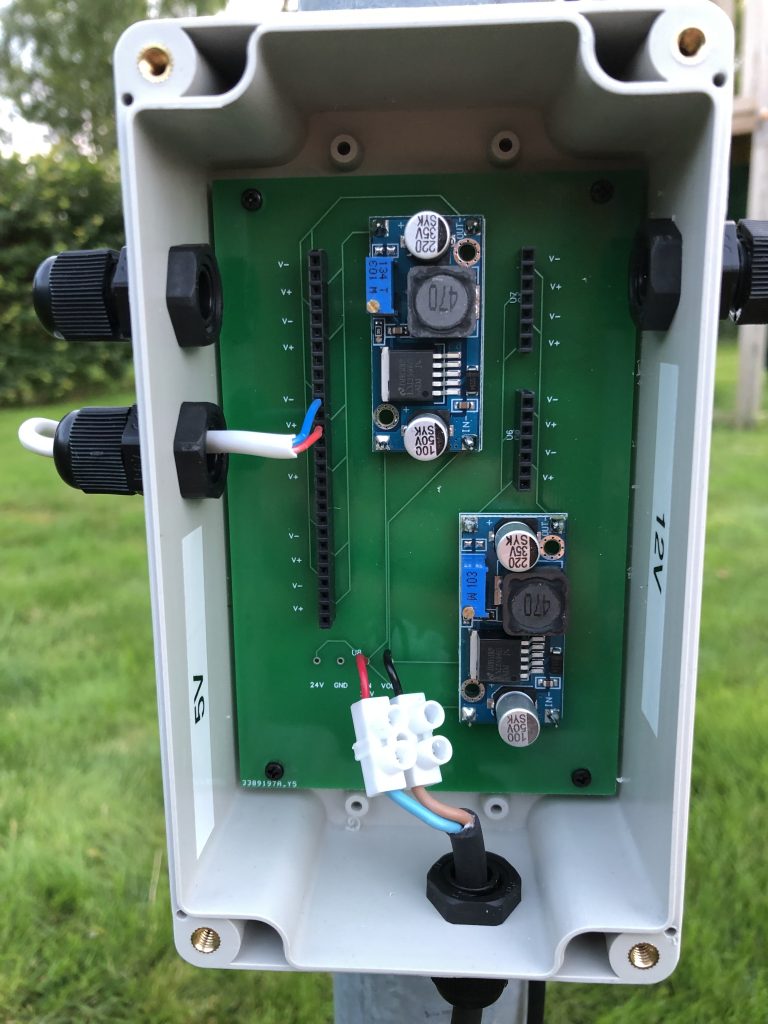
After soldering the components, placing it into the box and mounting it at the bottom of a pole supporting my weather station, the result looks like this.
PCB design perils
Note a few things. Most obviously, the holes intended for the terminal blocks have female headers soldered onto them instead. This is because I made a mistake designing the board. The holes are not big enough for the (typically 1 mm thick) pins of the terminal blocks. How did this happen? Even though the EasyEDA designer warns you to actually check when using publicly available design components, I only confirmed the distance between the holes without checking the diameter of the holes. Luckily, not all was lost. For my purposes, the headers will do as long as I use cables with solid copper wires to connect with them. Since the 24 V input is a wire with copper strands I can’t plug into the headers, I needed a slightly difference approach for that, as can be seen at the bottom of the box.
Linking everything together
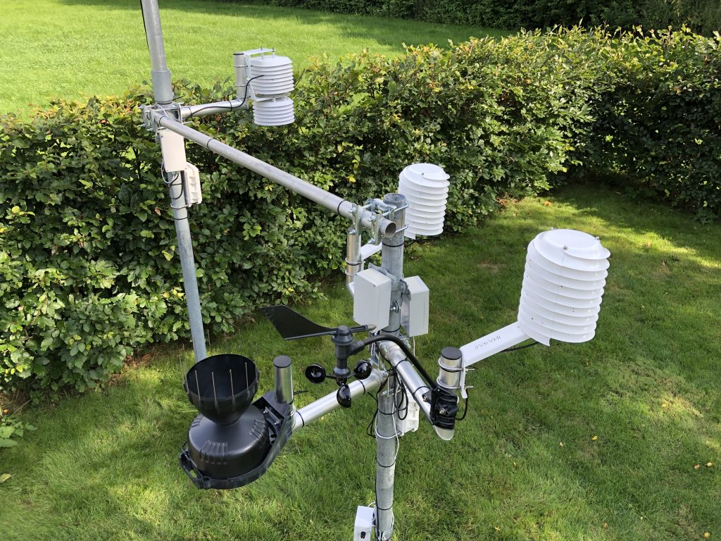
As of this moment, I have removed all my solar power sources and connected existing sensors to one of the 5 V sources. I added an extra aluminium pole (42 mm diameter) horizontally connecting the two support poles I had in place, creating a single structure. This allows me to easily connect anything on either side to the new power source. It also gives me a place to mount the Apogee TS-100, since the mounting bolt at the top requires a horizontal pole.
I am currently in the process of testing the TS-100, confirming I can vary the fan speed with the Wemos board the way I intended. I already designed and received the PCB I will be using as a controller (which in one place has the same design flaw mentioned above, but also not fatal). My next post will involve a partial review of the TS-100 and a discussion of the controller board.