
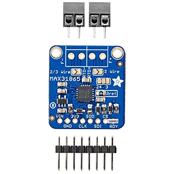
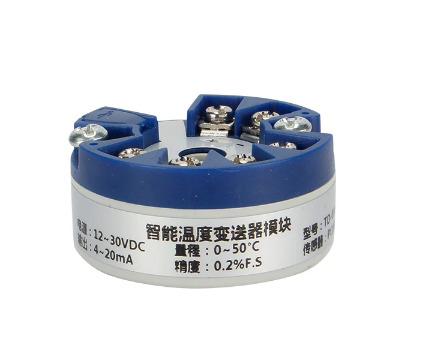
Since very recently I have two identical PT100 sensors set up inside the same fan-aspirated shield. The first sensor is read using the Adafruit MAX31865 breakout board, while the second is linked to a 4-20 mA current loop transmitter. In both cases, a Wemos D1 Mini microcontroller is used to process the signal. For the MAX31865 this is a digital reading, while the 4-20 mA is converted into a voltage signal read by the ADS1115 analog-to-digital converter.
The reason I went through the trouble of setting up the second transmitter, is that I wanted more certainty that I was really getting proper measurements from the MAX31865. Compared to the SHT35, which is housed inside a plastic probe, the PT100 readings are quite jumpy. There were a few theories I could come up with.
- EM noise. Somewhere along the line, the readings are affected.
- The MAX31865 just can’t deliver very good results
- The PT100 sensor itself is unstable
- The PT100 is just a lot more sensitive to temperature shifts, the inverse being that the SHT35 is not as sensitive as you’d want
Theory 3 is partially dismissed because the sensor does in fact provide very stable readings in an environment with a stable temperature. It may still be true that changes in temperature (and therefore resistance) cause erratic changes in resistance values. I am not sure if that makes sense.
As for theory 4, I have confirmed that the PT100 is indeed more sensitive than the SHT35. This can be seen on a daily basis when analyzing the temperature graphs. But I have also confirmed this a more controlled environment, where the SHT35 simply takes longer to respond to changes in temperature. This may be due to the sensor itself or the casing, or both.
Then theory 1 and 2. These can both be tested by adding a second PT100 with a different method of measurement. Hence the 4-20 mA current loop.
Based on the initial readings, things seem to point to both theories being false. Take a look at this graph for a random period of today.

Let me also include my primary SHT35 sensor measurements to the graph.
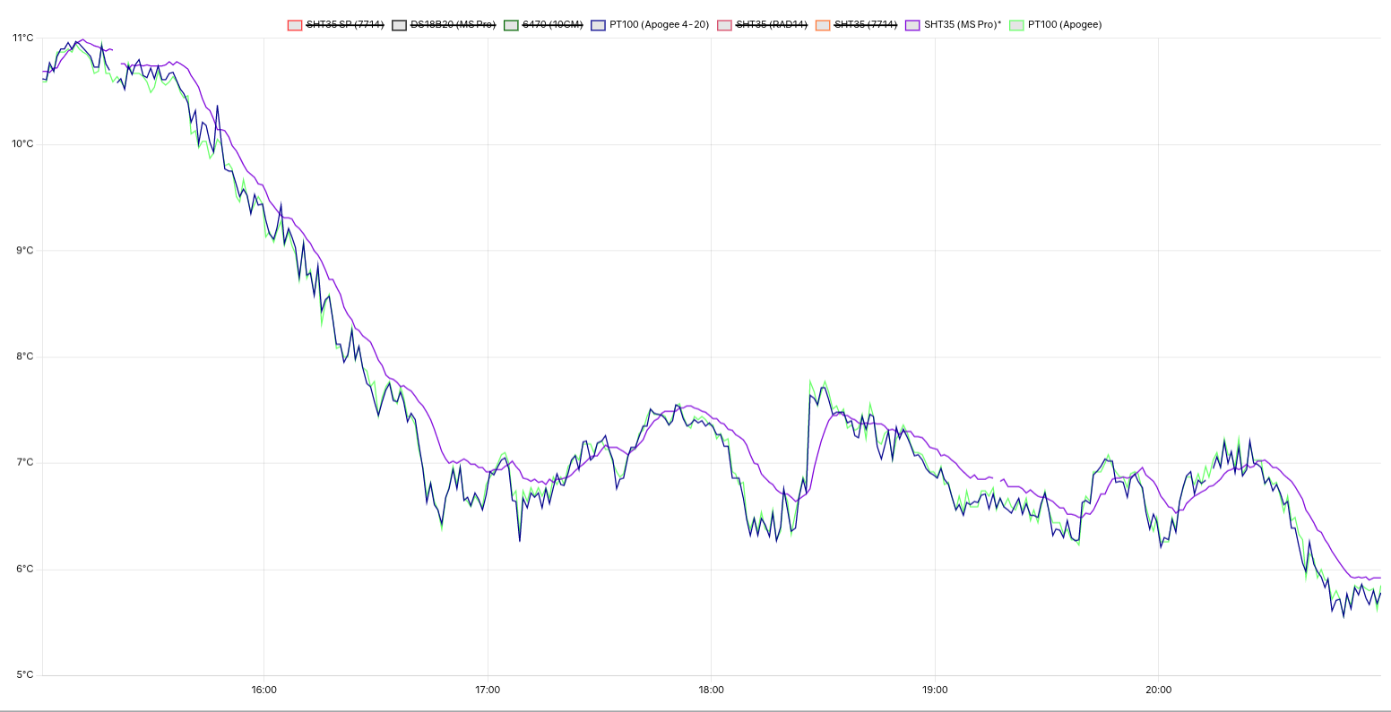
The second graph clearly shows the delayed response of the SHT35 (in purple). But it is also clear that the graphs for both PT100’s are in complete agreement. There are one or two deviations which could be attributed to noise. However, had this been the cause of the difference between the apparent ‘stable’ SHT35 and the ‘erratic’ PT100, my expectation would have been that there would be (significant) disagreement between the two PT100’s. Random noise would never cause identical patterns. Also, a second conclusion is that both the MAX31865 and the 4-20 mA transmitter are in agreement. Let me zoom in a bit more on 1 hour of measurements.
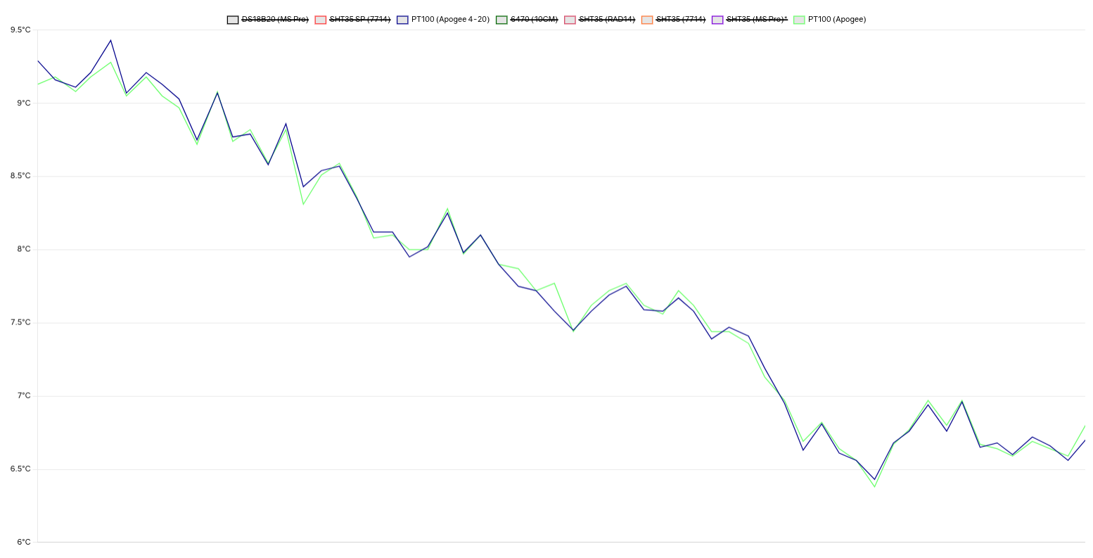
This graph shows jumps in temperature of up to 4-tenths of a degree within a single minute. Something the SHT35 very rarely shows. But both sensors agree that the temperature has indeed shifted as much as 0,4 degrees. So it seems hard to attribute this to the method of measurement.
What remains is the possibility that the PT100 sensors themselves somehow respond to extremely to temperature changes, and do so in the same way. The sensors are still a common factor. I feel I cannot exclude them as the cause apparent instability.
My current plan is to keep analyzing the behavior of the two sensors for a while. After that, I want to add another identical PT100 sensor and place it inside one of my passive radiation shields. It will be interesting to see if it behaves differently when there is not a steady air flow over it. Lastly, I want to try a different PT100 sensor. I will share results in another post.
Hello, interesting experiment. I did some experiments too with the max31865. I had some doubts too on the measurements and in the end i designed a pcb with an ads124s08 chip with 4 4-wire pt100 connections where i can plugin an wemos d1 mini that will send the measurements through mqtt.
Hi,
What a great blog you’ve got! I love it.
I’m in the middle of building my own weather station but I’m not as knowledgeable as you are.
My weather station would be based on an Arduino or ESP32 platform, so, in your opinion which temperature and/or humidity sensor would be the easiest to interface with the aforementioned platforms?
I want to keep it reasonably cheap (Maybe around $100 to $200 for a sensor) and expect an accuracy of around plus or minus 0.1 degrees C.
Your recommendations will be very welcome!
Thanks in advance and keep up the great work.
Cheers,
Luc (Melbourne, Australia)