
As I pointed out in my previous post on the AS3935 lightning detector, the AS3935MI library available through the Arduino IDE works quite alright. However, every time I boot the Wemos D1 Mini with it, I get a warning that the calibration of the resonance frequency failed.
As per the datasheet, the frequency needs to be within 3.5% of 500 kHz for optimal performance. So, between 482,5 and 517,5 kHz. Even after the automatic calibration the code provides, it would be below 480 kHz. This caused some skepticism in me about whether the calibration was being performed properly or if the correct value was being read.
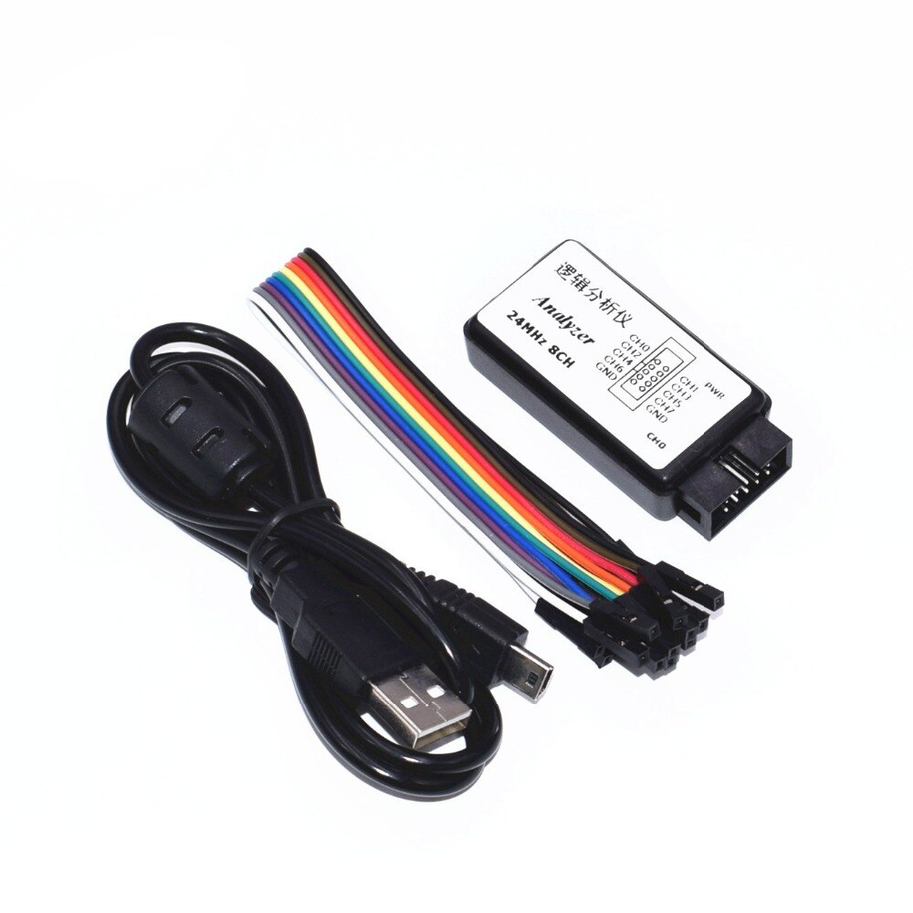
Now the AS3935 has a setting which allows you to read the frequency value from the IRQ pin. One way to then read the frequency is using an oscilloscope. These devices are not cheap and I don’t have the expertise to determine which one to get. An alternative is to use a logic analyzer. A simple tool which allows you to read the signal from the pin using some simple pc software. The analyzer I got is only 10 euros, or cheaper when you want to wait and order in from China.
There are bunch of articles and video’s explaining what a logic analyzer does. The bottom line for my simple case is that I can use it to read the IRQ pin and tune the AS3935. How does with work? In what follows I assume you’ve already connected the correct pins between the sensor and a Wemos D1 Mini in line with that I described here.
First, we need the software tool to connect with the logic analyzer. Mine happens to be compatible with Saleae Logic. An alternative is PulseView. Look for some simple video’s explaining how get it started.
Second, we connect the IRQ pin on the AS3935 to one of the available channels on the logic analyzer. This means that all pins in use on the AS3935 will be connected to the Wemos board, except the IRQ pin, which will be connected to the analyzer. The ground pin on the analyzer should then be connected to the ground on the Wemos D1 Mini.
Now we are set to read the frequency. But first, we need to instruct the AS3935 to actually start emitting the frequency signal on the IRQ pin, so the analyzer can pick it up. The AS3935MI library mentioned before has everything we need. In fact, the auto calibration procedure called during the setup stage of the sketch already calls the code we are going to need. The difference is the procedure tries different tuning settings within a 2 second period before ending the setup stage.
What I’ve done is strip the example code down to a simple setup which only initializes the AS3935 and then immediately starts displaying the frequency.
#include <Arduino.h>
#include <SPI.h>

#include <AS3935SPI.h>

#define PIN_IRQ 5
#define PIN_CS 15

AS3935SPI as3935(PIN_CS, PIN_IRQ);

void setup() {
  Serial.begin(9600);

  SPI.begin();

  if (!as3935.begin())
  {
    Serial.println("begin() failed. check your AS3935 Interface setting.");
    while (1);
  }

  //check SPI connection.
  if (!as3935.checkConnection())
  {
    Serial.println("checkConnection() failed. check your SPI connection and SPI chip select pin. ");
    while (1);
  }
  else
    Serial.println("SPI connection check passed. ");

    //set tuning capacitors, must be a value between 0 and 15
    as3935.writeAntennaTuning(0);

    // not sure if needed
    delayMicroseconds(100);

    as3935.writeDisplayOscillator();

  Serial.println("Initialization complete, showing frequency on interrupt");
}

void loop() {}
Before this code will work, we need to make a small adjustment to the AS3935MI library. As is, it does not allow sending the chip the necessary update. I added the writeDisplayOscillator() function. Obviously there are multiple ways to achieve the same thing.
In the library source, opening AS3935MI.h and add the following line somewhere.
void writeDisplayOscillator();Then, in AS3935MI.cpp, add the actual implementation.
void AS3935MI::writeDisplayOscillator() {
	writeRegisterValue(AS3935_REGISTER_DISP_LCO, AS3935_MASK_DISP_LCO, 1);
}
Calling writeDisplayOscillator() will now instruct the chip to start emitting the frequency on the IRQ pin.
Note that, per default, the value will be divided by 16. Hence, 500 kHz exactly would show up as 31,25 kHz.
There are 16 tuning settings. You can pass a value between 0 and 15 the writeAntennaTuning() function to try them all. Trying all settings means uploading a new sketch with a different value each time. After the Wemos boots, start capturing using the logic analyzer. A result like below is what you are looking for.
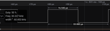
This is the result of what turns out to be the optimal setting, setting 0. The frequency of 30,227 kHz translates to (30,227 * 16) 483,6 kHz. This is just within the 3.5% range. Any other setting will only result in a lower frequency.
While the measured value is a bit better than what the library code suggested, I can conclude that it did choose the most optimal tuning setting. In other words, this whole endeavor, although it did give better insight into the exact frequency, was ultimately not necessary to get the AS3935 on the right tuning setting. The auto calibration works.