
During previous summers I have always been busy with temperature sensors and radiation shields. This year, I have shifted my focus to precipitation. The main reason why I find this interesting is that our warm seasons have seen quite a few dry spells over the past few years. This causes all sorts of issues, but I have few sensors that actually detect rain and ground moisture. My first project this August will be setting up a Hydreon RG-15 solid state rain sensor.
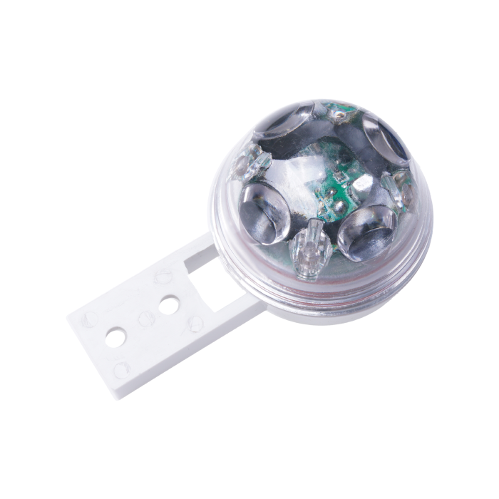
The RG-15 detects water drops using beams of infrared light. It’s been on my wish list for a while. Though it is not known for its accuracy (specifications say it can be off by 10% in “controlled environments”), what I like most about it is its ability to detect small amounts of rain. My Davis rain collector has a resolution of 0.2mm and will only detect rain when at least that amount has fallen. I also assume that, when the collector cone is dry, it will take some additional time before water actually starts dripping into the tipping spoon. This means that small amounts of rain will often go unnoticed or will only be detected after a significant amount of time has passed. The RG-15 offers a resolution of 0.02mm when you set some dip switches correctly. In the “tipping bucket” mode I will be testing, it gives virtual tips every time that amount of rain has been detected. This resolution is ten times better than the Davis. I hope this will allow me to detect more “rain events” than I do now.
Note that I will be using the J1 connector, which only offers this tipping bucket mode and is limited to giving me notifications whenever such a virtual tip occurs. The J2 connector has additional pins and allows for serial communication with the device. At first I thought that all useful information via the J2 serial interface could be inferred based on the virtual tips. But after a closer look, it looks like there may be more to it. It may offer the option to detect rain events even before the threshold of 0.02mm is reached. Serial communication via J2 will be part of another blog post.
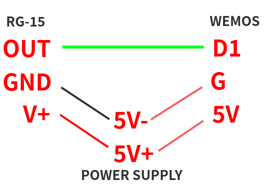
As for the J1 connection, I will (as always) be hooking up the RG-15 to a Wemos D1 Mini (ESP8266). The RG-15 accepts a 5-35 volt input, which is perfect since the D1 Mini runs on 5V itself. They can share the same power supply. (The assumption at the start is that the power supply, even though multiple controller boxes and sensor devices share it, should be stable enough not to cause any issues like false positives) Other than power, only 1 other pin is involved. Below I assume the reader has some basic experience using the D1 Mini or some other Arduino-type microcontroller. If that is not the case, details on most of what I mention can be easily found on the internet with a simple search.
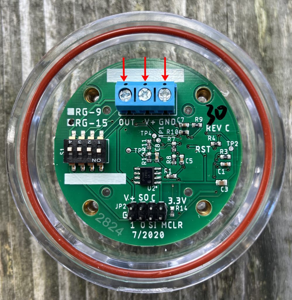
Let’s start with the connection between the RG-15 and the D1 Mini. In the image above, I’ve marked the blue screw terminal and its connectors called OUT, V+ and GND on the RG-15. This terminal is referenced as J1 in the documentation. V+ and GND are for the power supply which it shares with the D1 Mini. OUT is described as an Open Collector Output which “pulls to ground” whenever a “tip” is registered. (Note that this project is technically quite similar to reading the fan speed on the prototype Barani FARS. In that project the same principle is applied in order to detect fan cycles.)
A tip occurs whenever 0.02mm of rain has been detected (or 0.2mm depending on dip switch settings if a lower resolution is your preference). Whenever such a tip occurs, OUT makes a connection to ground. Such an event can be detected by using a digital pin (like GPIO5/D1) on the Wemos as input with the internal pull-up resistor enabled. Enabling this pull-up means that D1 will read HIGH by default, unless a connection is made to ground. When that happens, voltage will flow to ground rather than to D1, which causes D1 to read LOW. If we enable the pull-up, connect D1 to OUT, it will therefore read HIGH unless the RG-15 pulls OUT to ground during an event in which case D1 reads LOW.
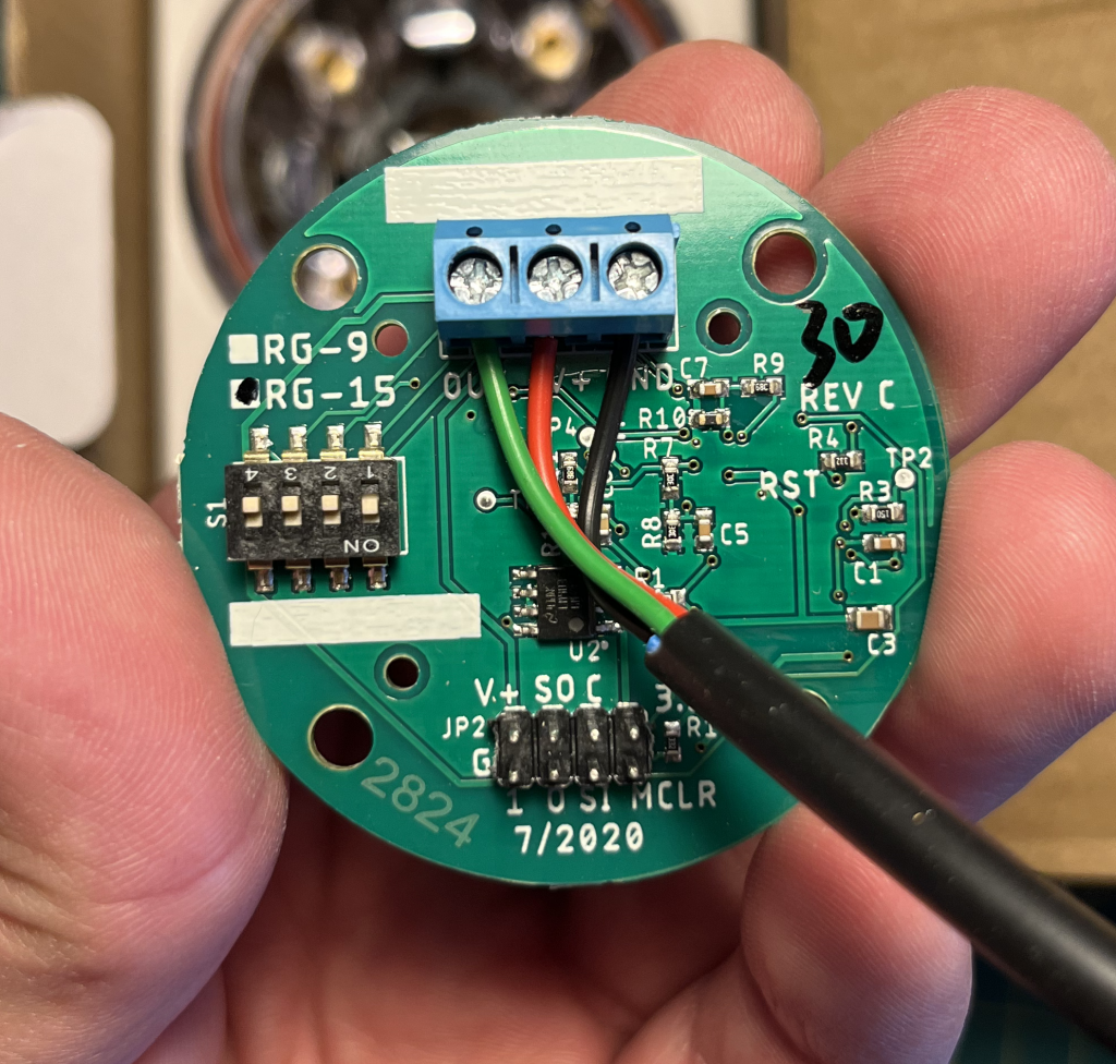
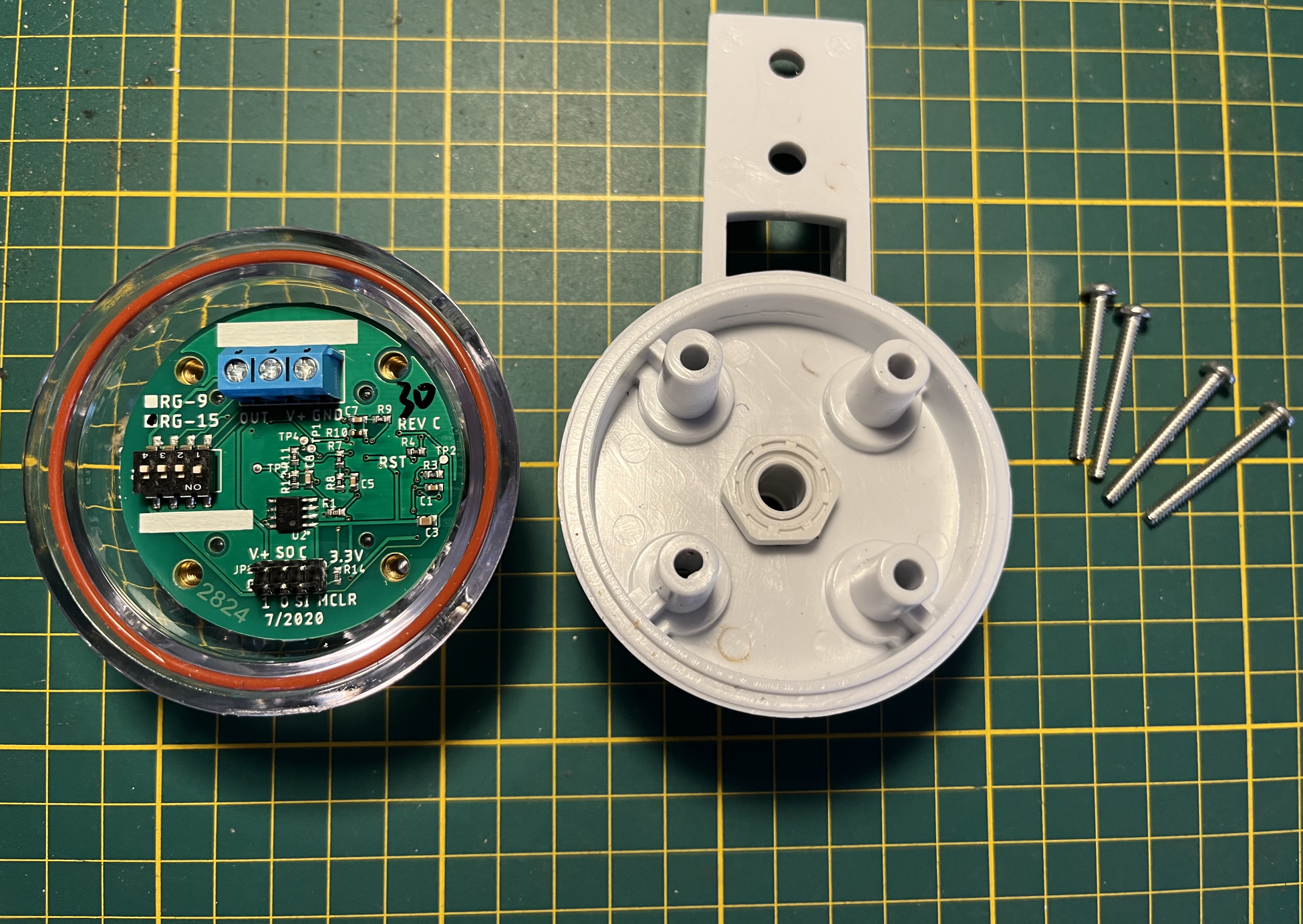
I use a simple cable with 3 cores and connected the black wire to GND, red to V+ and green to OUT. Below is the Wemos D1 Mini contained within its waterproof controller box.
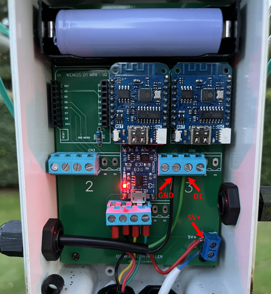
The relevant D1 Mini is the one on the right. You can see the red wire connected to the power supply 5V+. The black wire could have been connected to 5V-, but there is more room in the light blue terminal and the ground connector there is linked to the main ground of the power supply 5V- anyway. Green is connected to digital pin D1.
The coding is, at least in principle, simple too. We need a function that fires each time the RG-15 “tips”. That is, when D1 reads LOW. That function looks like this.
const uint32_t DEBOUNCE_TIME = 50000; // 50 ms
volatile uint32_t lastTipEvent = 0; // micros() of the last tip event
const size_t MAX_EVENTS = 2048;
volatile uint32_t tipEvents[MAX_EVENTS]; // in ms

//

void ICACHE_RAM_ATTR tipHandler() {
  uint32_t now = micros();
  if ((uint32_t)(now - lastTipEvent) >= DEBOUNCE_TIME) {
    Serial.println("Tip detected!");

    lastTipEvent = now;

    if (tipCounter < MAX_EVENTS) {
      tipEvents[tipCounter++] = millis();
    }
  }
}
The actual function is tipHandler(). It uses 5 global variables.
DEBOUNCE_TIME is a good practice and involves disregarding events when they are fired too close to each other (in this case 50 ms). Though the RG-15 pulling to ground will not involve an actual mechanical bounce, a debounce ensures that if for whatever reason the function is triggered multiple times for one event (we assume that is the case when it happens within 50 ms), we don’t count it more than once.
The value for lastTipEvent actually allows us to compare the time of the current triggering with the last time the function was properly triggered.
We define an array of MAX_EVENTS long. This is the maximum number of events that will be retained by the buffer. That is (2048 * 0,02mm) 40,96mm of rain. Considering that the buffer should be emptied every few seconds, that’s just a silly large number. A downpour at a rate of 100mm per hour will only trigger 1,4 events per second.
Lastly the actual array containing the events is tipEvents and tipCounter tracks the number of events that were added to it.
The tipHandler() function does a few simple things. First it gets the time of the event in microseconds.
uint32_t now = micros();It then checks if the event should be considered or not. If the last event is more than 50 ms ago (the value of DEBOUNCE_TIME) it will be considered a valid event.
if ((uint32_t)(now - lastTipEvent) >= DEBOUNCE_TIME) {Then the value of lastTipEvent is set to that of the current event.
lastTipEvent = now;Finally, if the limit of MAX_EVENTS for the tipEvents buffer has not been reached according to the value of tipCounter, the milliseconds value of the current event is added to the array and the tipCounter value is incremented.
    if (tipCounter < MAX_EVENTS) {
      tipEvents[tipCounter++] = millis();
    }
To make this code actually execute upon the RG-15 pulling to ground and D1 going LOW, we need to initialize a few things in the setup() function of the sketch.
int INTERRUPT_PIN = 5; //D1

//

void setup() {
  Serial.begin(9600);

  Serial.println("Executing setup...");

  pinMode(INTERRUPT_PIN, INPUT_PULLUP);
  Serial.println("Pulled INTERRUPT_PIN high");

  uint32_t now = micros();
  attachInterrupt(INTERRUPT_PIN, tipHandler, FALLING);
  Serial.println("Attached interrupt");
}
Besides running some logging, this code does 2 things. Using the pinMode function, it takes the interrupt pin (which is D1) and sets it to be used as INPUT while enabling the pull-up at the same time (using INPUT_PULLUP mode). D1 is now reading HIGH. Second, an interrupt function is attached to the D1 pin using attachInterrupt. That function is tipHandler() and we indicate that it should be triggered when the pin is FALLING. That is, when is goes from HIGH to LOW.
This is all the code that is needed to start detecting tip events.
As per usual, I also want the events detected to be posted to my meteodrenthe.nl server. The interrupt function itself is supposed to be a very light weight function. It cannot also do things like connecting to WiFi and posting data using http clients. For that we need the loop() function.
Rather than have a very busy loop that constantly checks for events, I thought it would make sense to send events in batches. Especially during heavy rainfall, posting immediately might involve posting data as frequently as more than once a second. But even though I store events to be sent a bit later, I would still like to have exact timestamps for each event. This is where things get slightly more complicated. The milliseconds value we register for the events is the number of milliseconds that have passed since boot, not an actual epoch milliseconds value. The Wemos D1 Mini has no direct knowledge of the current time. In order to know the timestamp of an event, we need to synchronize with an NTP server upon boot. The NTP sync itself is quite simple.
configTime(0, 0, "pool.ntp.org", "time.google.com");This code runs an asynchronous process that retrieves the time via pool.ntp.org, with time.google.com as backup. It passes 0 for offset from UTC and 0 offset for daylight saving purposes. In other words we request UTC time.
We need to connect to WiFi before running this line. I will not share my connectToWiFi() function here. Connecting to your network is well documented online.
A complication is that connecting to WiFi and retrieving time data may take a few seconds. Since we do not want to miss any potential events that might occur shortly after a boot, the interrupt is attached before NTP sync. This is the reason why the events in the code above are stored as system milliseconds (using millis()) rather than epoch milliseconds (which may not be available for events that happen within a few seconds after boot).
In order to determine the epoch milliseconds value retroactively, we need to store the system milliseconds when NTP sync happened. For simplicity I also store the epoch milliseconds at that instant. For this purpose, we can define a callback function that runs when the NTP sync completes. Here are some code snippets.
extern "C" {
  #include <sntp.h>   // exposes sntp_stop()
}

uint32_t systemMillisAtNtpSync;
uint64_t epochMillisAtNtpSync;

//

int64_t getEpochMillis() {
  struct timeval tv;
  gettimeofday(&tv, NULL);
  return (tv.tv_sec * 1000LL + (tv.tv_usec / 1000LL));
}

void onTimeSync() {
  systemMillisAtNtpSync = millis();
  epochMillisAtNtpSync = getEpochMillis();
  sntp_stop();
  Serial.println("Time was synced with NTP server");
}
This onTimeSync() callback function sets the value of systemMillisAtNtpSync to the milliseconds since system boot and the value of epochMillisAtNtpSync to the current epoch milliseconds value. Then it calls sntp_stop() to prevent any future automatic syncs that could potentially cause conflicts. Note the #include at the top of the snippet for that purpose. If this function is not called the same time sync will occur every hour by default. (I will admit that I base this on some forum references and I have not delved into the source code for this, and very limited documentation seems available)
The getEpochMillis() function uses the gettimeofday() function to get the current timestamp down to microsecond precision and converts that to milliseconds.
The updated setup() function now looks like this.
void setup() {
  Serial.begin(9600);

  Serial.println("Executing setup...");

  pinMode(INTERRUPT_PIN, INPUT_PULLUP);
  Serial.println("Pulled INTERRUPT_PIN high");

  attachInterrupt(INTERRUPT_PIN, tipHandler, FALLING);
  Serial.println("Attached interrupt");

  connectToWiFi();
  settimeofday_cb(onTimeSync);
  configTime(0, 0, "pool.ntp.org", "time.google.com");

}
So now we have enough information to calculate the exact epoch milliseconds for each event.
This is the loop.
void loop() {
  if (systemMillisAtNtpSync > 0) {
    static uint32_t eventSnapshot[MAX_EVENTS];
    size_t countSnapshot = 0;

    noInterrupts();

    countSnapshot = tipCounter;

    if (countSnapshot > 0) {
      memcpy(eventSnapshot, (const void*)tipEvents, countSnapshot * sizeof(uint32_t));
      tipCounter = 0;
    }

    interrupts();

    if (countSnapshot > 0) {
      postEvents(eventSnapshot, countSnapshot);
    }
  }

  delay(5000);
}
The loop runs every 5 seconds. Only after the NTP sync has happened will it actually start posting events to the server.
if (systemMillisAtNtpSync > 0) {Then we define the variables which will contain snapshot values of tipCounter and tipEvents. The noInterrupts() function is called which temporarily disables the interrupt function from running. This prevents any potential modification to the data while we are trying to create a snapshot from it. No tip events will be detected for a very short amount of time. Just enough to do the following.
A snapshot value of the tipCounter is set and a copy is made of all the current events.
    countSnapshot = tipCounter;

    if (countSnapshot > 0) {
      memcpy(eventSnapshot, (const void*)tipEvents, countSnapshot * sizeof(uint32_t));
      tipCounter = 0;
    }
The value of tipCounter is reset to 0. The tipEvents array is not cleared as it is not necessary to do so. Each loop, the tipCounter dictates which entries are valid.
Immediately afterwards, interrutps() is called, which reactivates our interrupt. Then, if the the tipCounter was greater than 0, we run postEvents(), which contains all HTTP post logic specific to my case.
    if (countSnapshot > 0) {
      postEvents(eventSnapshot, countSnapshot);
    }
A delay of 5000 ms is added, after which the loop runs again.
The postEvents() function, as said, contains code specific to my case. The only important function remaining is this:
uint64_t getEpochMillisFromEventMillis(uint32_t eventMs) {
  if (systemMillisAtNtpSync > 0) {
    int32_t offsetMs = eventMs - systemMillisAtNtpSync;
    return epochMillisAtNtpSync + offsetMs;
  } else {
    return 0;
  }
}
This function converts the event timestamp (in milliseconds since boot) to epoch milliseconds. It does this by:
- Subtracting the system milliseconds value at the time of NTP sync from the event milliseconds value, giving the elapsed time since NTP sync.
- Adding that elapsed time to the epoch milliseconds recorded at NTP sync, giving the event’s epoch time.
For example: if NTP sync occurs 5 seconds after boot and an event occurs 30 seconds after boot, the elapsed time since sync is 25 seconds (30 − 5). Adding 25 seconds to the NTP sync epoch milliseconds gives the event epoch time.
One last consideration is how long the code keeps running. The D1 Mini has to be active constantly in order to detect every event. But keeping it running indefinitely can cause complications. Consider the maximum value of the response of millis(). As the documentation indicates, it “will overflow (go back to zero), after approximately 50 days”. To keep things simple, I want to reboot at least before those 50 days have passed. Since we start detecting almost immediately upon boot, the risk of losing events during reboot is small. Still, even though we’re typically talking about just a fraction of a second, I’d rather not restart when there have been any recent tip events.
I added two constants for the millisecond values of 1 week and 30 minutes to the code, as well as a new variable for tracking the millisecond value of the last event.
constexpr uint32_t WEEK_MS = 604800000;
constexpr uint32_t THIRTY_MIN_MS  = 1800000;
volatile uint64_t lastTipEventMillis = 0;
And this to the end of the loop.
  uint64_t nowMillis = millis();

  if (nowMillis > WEEK_MS && nowMillis - lastTipEventMillis > THIRTY_MIN_MS){
    // been running more than 1 week AND no event in last 30 minutes
    ESP.restart();
  }
Additionally I have changed a little bit of code in the interrupt function.
  if (tipCounter < MAX_EVENTS) {
      uint64_t eventTimestamp = millis();
      lastTipEventMillis = eventTimestamp;
      tipEvents[tipCounter++] = eventTimestamp;
    }
Now, the device will restart every time a full week has passed and no tip events have occurred for at least 30 minutes.
This is the full code, excluding the WiFi and HTTP POST implementation.
//

#include <ArduinoJson.h>
extern "C" {
  #include <sntp.h>   // exposes sntp_stop()
}

//

constexpr uint32_t WEEK_MS = 604800000;
constexpr uint32_t THIRTY_MIN_MS  = 1800000;

//

uint32_t systemMillisAtNtpSync;
uint64_t epochMillisAtNtpSync;

int INTERRUPT_PIN = 5; //D1
const uint32_t DEBOUNCE_TIME = 50000;
const size_t MAX_EVENTS = 2048;
volatile uint32_t tipEvents[MAX_EVENTS];
volatile uint32_t tipCounter = 0;
volatile uint32_t lastTipEvent = 0;
volatile uint64_t lastTipEventMillis = 0;

void ICACHE_RAM_ATTR tipHandler() {
  uint32_t now = micros();
  if ((uint32_t)(now - lastTipEvent) >= DEBOUNCE_TIME) {
    Serial.println("Tip detected!");

    lastTipEvent = now;

    if (tipCounter < MAX_EVENTS) {
      uint64_t eventTimestamp = millis();
      lastTipEventMillis = eventTimestamp;
      tipEvents[tipCounter++] = eventTimestamp;
    }
  }
}


void setup() {
  Serial.begin(9600);

  Serial.println("Executing setup...");

  pinMode(INTERRUPT_PIN, INPUT_PULLUP);
  Serial.println("Pulled INTERRUPT_PIN high");

  attachInterrupt(INTERRUPT_PIN, tipHandler, FALLING);
  Serial.println("Attached interrupt");

  connectToWiFi();
  settimeofday_cb(onTimeSync);
  configTime(0, 0, "pool.ntp.org", "time.google.com");
}

void loop() {
  if (systemMillisAtNtpSync > 0) {
    static uint32_t eventSnapshot[MAX_EVENTS];
    size_t countSnapshot = 0;

    noInterrupts();

    countSnapshot = tipCounter;

    if (countSnapshot > 0) {
      memcpy(eventSnapshot, (const void*)tipEvents, countSnapshot * sizeof(uint32_t));
      tipCounter = 0;
    }

    interrupts();

    if (countSnapshot > 0) {
      postEvents(eventSnapshot, countSnapshot);
    }
  }

  uint64_t nowMillis = millis();

  if (nowMillis > WEEK_MS && nowMillis - lastTipEventMillis > THIRTY_MIN_MS) {
    ESP.restart();
  }

  delay(5000);
}

void onTimeSync() {
  systemMillisAtNtpSync = millis();
  epochMillisAtNtpSync = getEpochMillis();
  sntp_stop();
  Serial.println("Time was synced with NTP server");
}

int64_t getEpochMillis() {
	struct timeval tv;
	gettimeofday(&tv, NULL);
	return (tv.tv_sec * 1000LL + (tv.tv_usec / 1000LL));
}

uint64_t getEpochMillisFromEventMillis(uint32_t eventMs) {
  if (systemMillisAtNtpSync > 0) {
    int32_t offsetMs = eventMs - systemMillisAtNtpSync;
    return epochMillisAtNtpSync + offsetMs;
  } else {
    return 0;
  }
}

void postEvents(const uint32_t* timestamps, size_t count) {
  // case specific implementation
}

void connectToWiFi() {
  // case specific implementation
}
I will be adding posts about the mounting bracket I printed for the RG-15 and my actual experiences with it as a rain detection sensor.