
In my never ending quest for better temperature readings – or other ways of doing so, at least – I’ve begun trying other sensors than the SHT35. One of them is the PT100. Platinum resistance sensors are supposed to be very accurate. They are used in many different situations, from laboratory settings to industry. And in weather stations weather stations as well. I noticed, for example, that Barani Designs has a sensor based on the PT100. A lot cheaper sensors are readily available.
At first, the initial required wiring seemed daunting. From my perspective a lot of wires and resistors. See this project, for example. I do not have the expertise to go into any details, but the bottom line is that the signal value being read (specifically the resistance, changing with temperature) needs to be amplified in order to get the precision required. Wiring this all by myself looked like quite a challenge.
Luckily, I quickly noticed there were solutions out there to simplify the connection between the PT100 and my go to Wemos D1 Mini micro controller. Specifically the Adafruit MAX31865 ‘resistance-to-digital-converter’. It’s out there by other manufacturers too and is very affordable. Especially considering the effort it saves.
Wiring
Hooking up a MAX31865 requires soldering some pin headers as well as one or two solder bridges, depending on if you have a 2, 3 or 4 wire PT100. I started out with a 3 wire version. Adafruit as a very good tutorial to get wiring done properly. There is no need to repeat everything here.
The part requiring the most attention to detail is soldering the bridges and – something I had not done before – cutting the ‘thin trace’ on one side of a two way bridge. The red circle indicates where cutting is supposed to happen (for a 3 wire PT100!) in this image from the Adafruit tutorial.
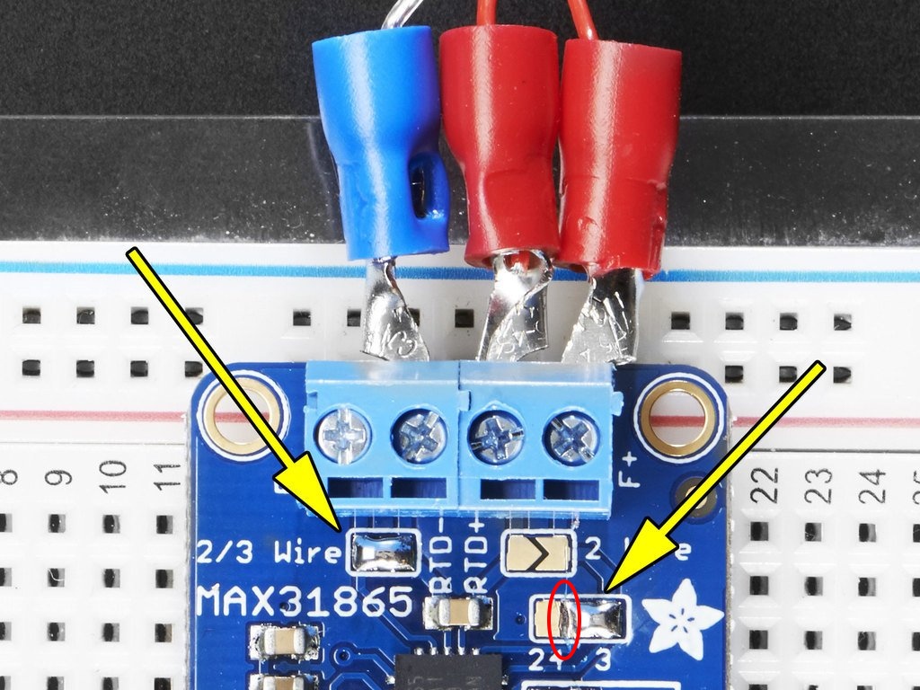
I didn’t get this right the first time I tried this, and my code ending up giving me errors.
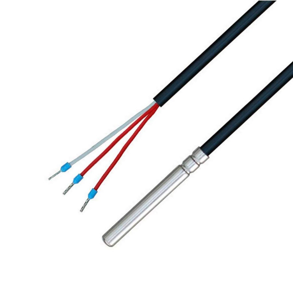
The image above also indicates how the PT100 wires connect with the MAX31865. In my case, the blue wire is white.
The other side of the connection with the Wemos D1 Mini requires an SPI interface. That means 6 wires connected to the board. Two of those are power (3.3 or 5V) and ground. The four other pins are called CLK, SDO, SDI and CS. Those match up with the SCLK, MISO, MOSI and CS pins for the SPI interface. The dedicated hardware pins for that interface on the Wemos D1 Mini are D5 through D8. But since the MAX31865 also offers ‘software SPI’, any available GPIO is OK to use. In my case, I happened to connect CS to a non standard pin D2. This is fine, as long as you indicate this in your code.
| Wemos D1 | MAX31865 |
|---|---|
| 3V | 3V3 |
| G | GND |
| CLK | D5 |
| SDO | D6 |
| SDI | D7 |
| CS | D2 |
Code
The Adafruit library for the MAX13865 can be found searching the Arduino IDE library manager.

The library has one example sketch. It works with hardly any adjustments. Only one line of code should be changed.
// Use software SPI: CS, DI, DO, CLK
Adafruit_MAX31865 thermo = Adafruit_MAX31865(10, 11, 12, 13);
The sensor library is initialized using the GPIO 10 through 13. Since the Wemos board does not have GPIO 10 or 11, other pins should be chosen. In my case, the line is this:
Adafruit_MAX31865 thermo = Adafruit_MAX31865(4, 13, 12, 14);These numbers translate to D2, D7, D6 and D5. Once again, these are not all hardware SPI pins, but this is possible because the library can do software processing of the bits sent over the wires.
The sketch can be uploaded as is now, and the serial log should quickly be flooded with messages including temperature readings. How the code is adapted to fit its use depends on each situation. As always, I run a loop which reads the value and then does an HTTP call to a Raspberry Pi on a local network.
PT100 performance
For my first project, I ordered a PT100 from Amazon without much direction or any idea how it would perform. My first choice wasn’t a lucky shot. For starters, it read about 1 degree above expected values. Consistently though, so subtracting 1 full degree from the readings yields a very acceptable result. (Update: after more testing I came to realize this was mostly due to inaccuracies in the MAX31865 clone I was using, rather than the sensor. See my other posts on reading the PT100 for more details.) What is also noticeable is that readings are not very stable. Compare the graph below with the PT100 in blue and an SHT35 in purple. The blue line is erratic.
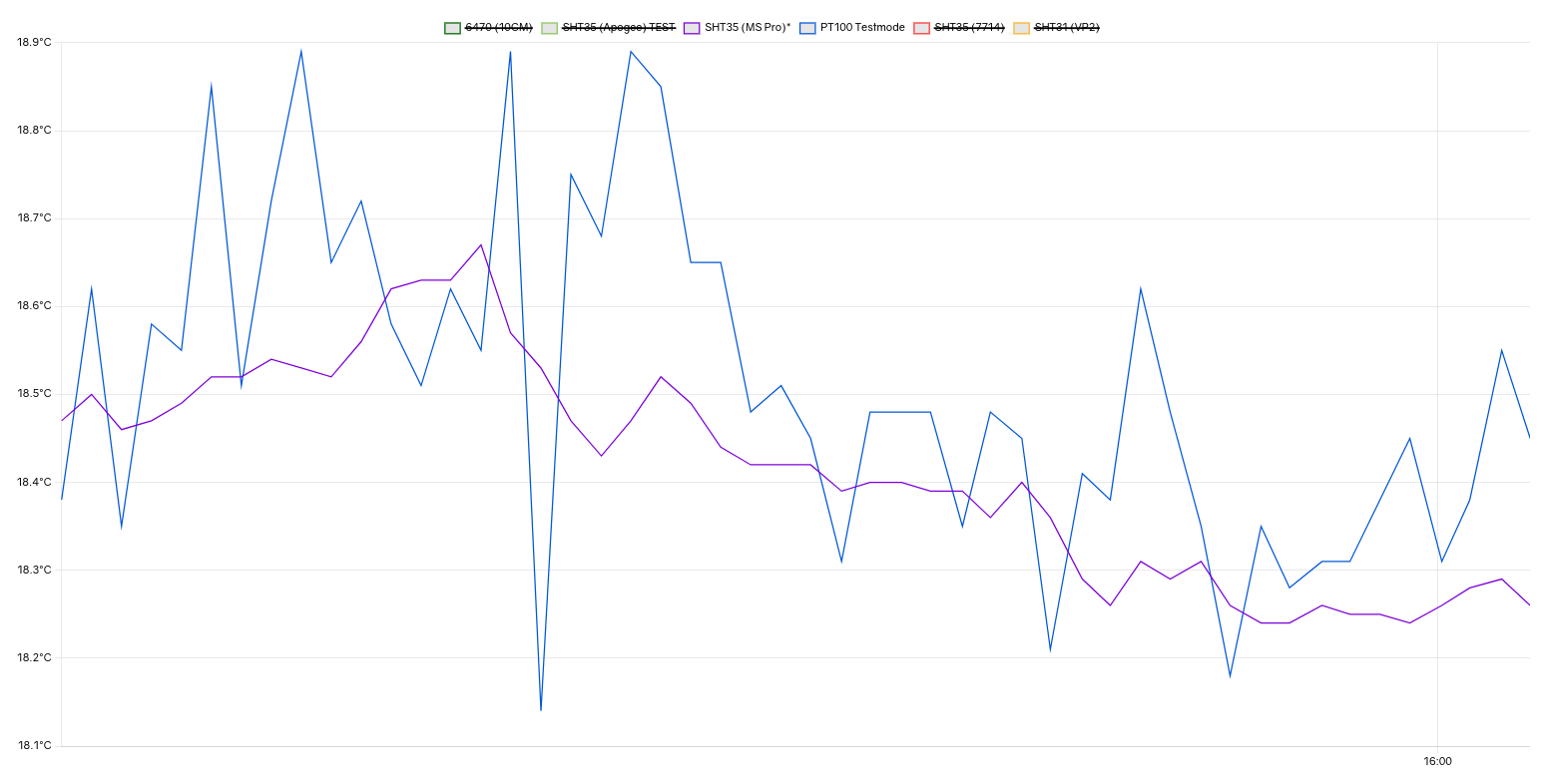
Before I draw any final conclusions, I will be testing additional (supposedly higher quality) PT100’s. I will be sharing results in other posts.